JimW did this Tilt Decoupling 14 April; those values he came up with have managed to survive and were still in the CPS Align Matrix. Since we've done lots of changes in many places, we thought a check of tilt decoupling was in order. This morning I repeated the measurement and adjusted the numbers around these historic values. I changed both RX & RY decouple numbers at the same time during the tests.
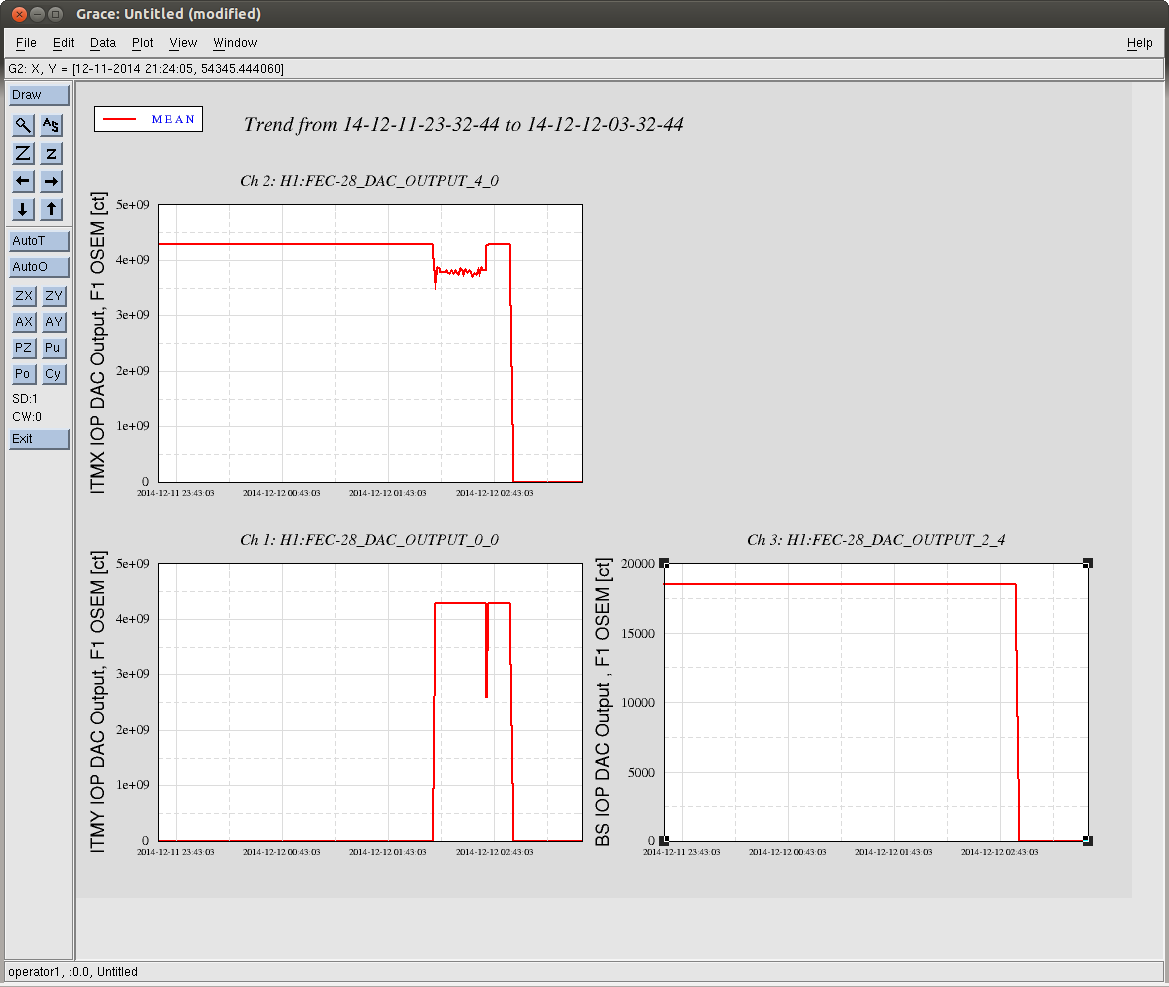
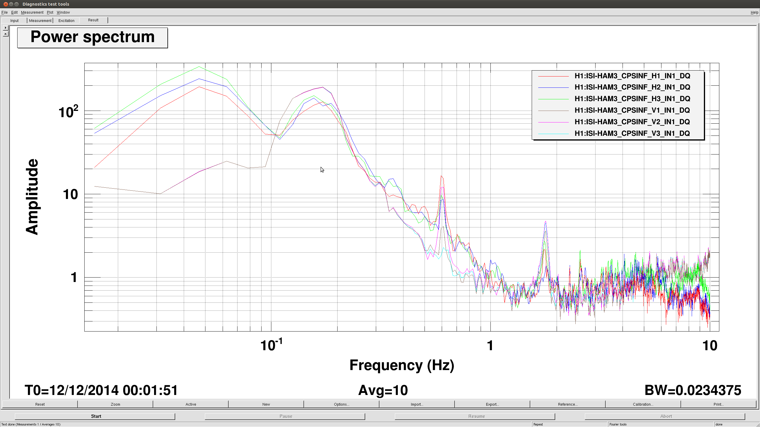
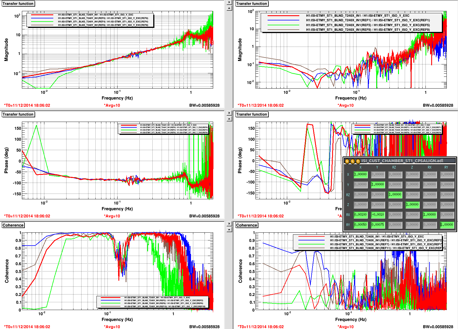
The first attached is the results for driving in the Y direction. The left column is for the in line coupling; that is, pitching response adjusted by the RX-Y component of the ALIGN matriix. The right column shows the cross response--rolling about the Y axis adjusted by the RY-Y Matrix element.
The blue traces are with the original values, -.001/.0005 for RX/RY to Y elements. Green is the change to -.0015/.00075; brown are with the elements at -.0005/.000 for RX/RY.
The red traces are with the final desired values. Looking at the left inline values, the original blue trace with RX-Y at -.001 looks best. For the cross term RY-Y, it looks best at .00075 shown on the green trace--notice the greatly reduced coherence and lowered amplitude in the lower right and upper right plots respectively. When these 'best' values are used for the red results, things don't look quite as good as the green and the blue but may be the best compromise. This really shows the couplings here and the pain given the length of these measurements.
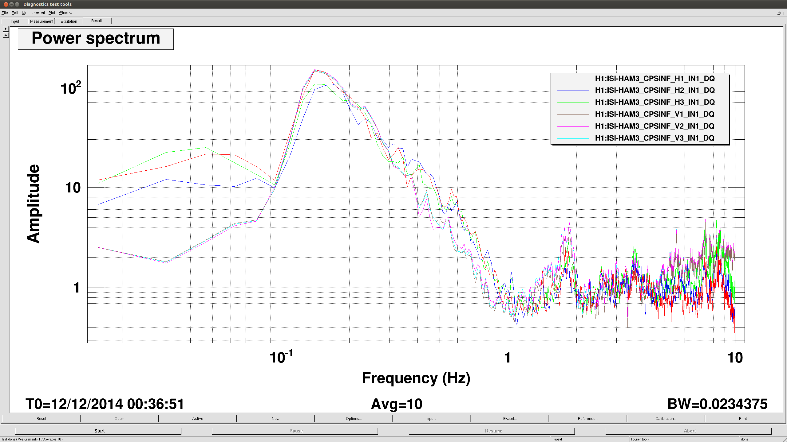
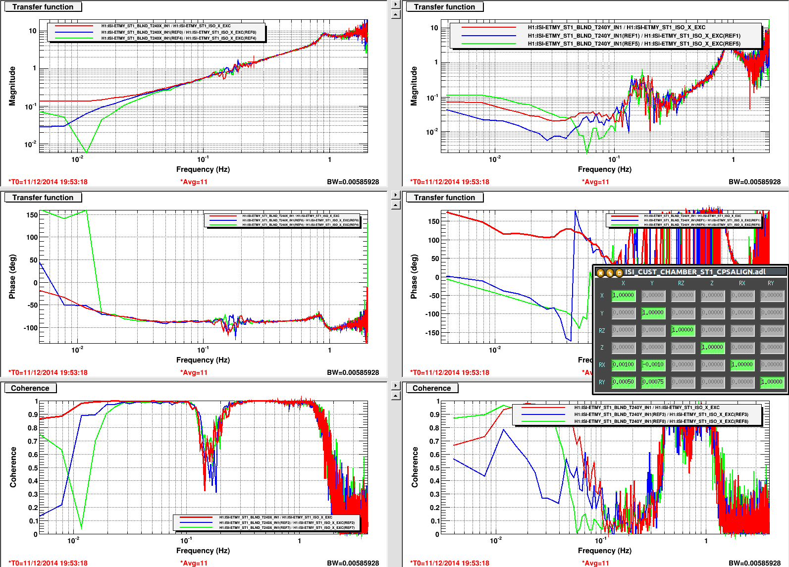
The second attachment shows driving in X. The blue curves show the original values for RX-X & RY-X. These are the best numbers as my bracketing around these makes the coupling higher seen in the green and red curves: The left column has the blue most linear and in the right column you see the lowest coherence and magnitude for the blue as well.
Templates for these measurements are in /ligo/svncommon/SeiSVN/seismic/BSC-ISI/H1/ETMY/Data/Transfer_Functions/Measurements/Tilt_Decouple/