daniel.sigg@LIGO.ORG - posted 13:20, Friday 12 December 2014 (15588)
BDIV EY/HAM1 tested
Looking at the sensor readbacks they seem to work.
Looking at the sensor readbacks they seem to work.
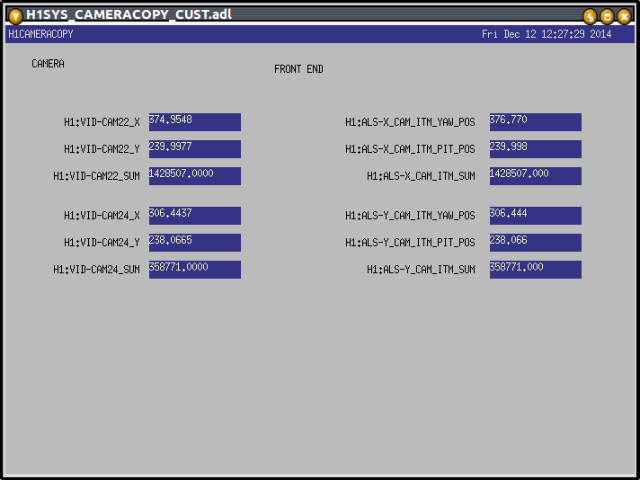
At Daniel's request I extended my cameracopy.py script to also copy the ITMX green digital video data (centroid position and sum) to the ALS-X front end.
I have documented this system on the CDS wiki https://lhocds.ligo-wa.caltech.edu/wiki/CameraCopy
I have created an MEDM, accessible from the sitemap SYS pull down (screen shot attached).
Dave O, Greg, Elli
Yesterday we tried to realign the Hartmann sensors in the corner station. This is because 14-11-12 17:15:00 the SR3 mirror changed alignment which threw out the HWS alignment. We found the alignment is now so bad the periscopes will have to be moved. I still need to do this. If the alignment of the SRC, BS, or ITms changes again we will have to realign the HWS again.
Are there any photos of the current positions of the green beams at the HWS periscopes?
Vent prep: While the commissioners were at a stopping point, I made a new h1susetmy_safe.snap file and committed it to the svn. The ETM was restored to their working configuration afterwards.
K. Venkateswara,
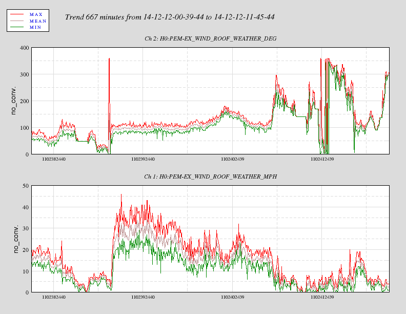
As reported yesterday, winds were gusting at 60 mph, at the corner station and roughly 40 mph at EX. They were mostly blowing across, ~ along Y direction for EX. I've attached ASD plots showing the tilt-subtraction during the period with higher wind speeds (GPS time 1102388000 - 1102403000), and the low-wind period (1102408000 - 1102413000).
The residual after tilt-subtraction is much higher during the windy period than without. But it is possible that the floor is being displaced that much more by the wind. The high-wind period drove up the resonance of the BRS, which is why the harmonics of the beam-balance are visible in the low-wind period. But otherwise the residual is as low as during other quiet periods.
Vent of BSC10 scheduled for Monday morning, door removal on Tuesday
Request for laser safe at end Y before Monday morning
2nd cleaning of BSC10 this morning
Purge air needs to be turned on this morning
Request to align end Y PCAL sometime during vent

CDS
Cabling in beer garden
Putting v6 AA boards back in chassis
Repair of ESD connectors next week

SEI
BRZ subraction on BSCs

3IFO
Corey and Suresh working on ISC kits in squeezer bay
model restarts logged for Thu 11/Dec/2014
2014_12_11 20:16 h1iopsusb123
2014_12_11 20:17 h1iopsusb123
2014_12_11 20:17 h1susitmx
2014_12_11 20:19 h1susbs
2014_12_11 20:19 h1susitmy
No unexpected restarts. Restart of h1susb123 to clear DAC problem. Conlog frequently changing channels list attached.
J. Kissel

These, damped, TOP2TOP, transfer functions complete the acceptance measurement suite for the H1 SUS ITMs (see LHO aLOG 14729 for the rest of the suite). For this Phase 3B measurement, the chamber is at vacuum, the HPI and ISIs are damped and isolated, and the SUS itself is damped.

The main chain transfer functions look exactly as expected with the LHO filter configuration that its been left in (see recent modeling efforts, and discussion of LLO filter design in LHO aLOG 14959). The reaction chain, in it's sad, sorry, copy-of-a-bad-copy, 2011, state looks like very very little thought has gone into their loop design. This is true, because it doesn't seem to matter for IFO noise or control. Some day we'll get to re-designing these loops just so they don't look so aesthetically displeasing.

Raw .xml files live here:
/ligo/svncommon/SusSVN/sus/trunk/QUAD/
H1/ITMX/SAGM0/Data/2014-12-11_0429_H1SUSITMX_M0_L_WhiteNoise.xml
H1/ITMX/SAGM0/Data/2014-12-11_0429_H1SUSITMX_M0_P_WhiteNoise.xml
H1/ITMX/SAGM0/Data/2014-12-11_0429_H1SUSITMX_M0_R_WhiteNoise.xml
H1/ITMX/SAGM0/Data/2014-12-11_0429_H1SUSITMX_M0_T_WhiteNoise.xml
H1/ITMX/SAGM0/Data/2014-12-11_0429_H1SUSITMX_M0_V_WhiteNoise.xml
H1/ITMX/SAGM0/Data/2014-12-11_0429_H1SUSITMX_M0_Y_WhiteNoise.xml
H1/ITMX/SAGR0/Data/2014-12-11_0545_H1SUSITMX_R0_WhiteNoise_L_0p1to50Hz.xml
H1/ITMX/SAGR0/Data/2014-12-11_0545_H1SUSITMX_R0_WhiteNoise_P_0p1to50Hz.xml
H1/ITMX/SAGR0/Data/2014-12-11_0545_H1SUSITMX_R0_WhiteNoise_R_0p1to50Hz.xml
H1/ITMX/SAGR0/Data/2014-12-11_0545_H1SUSITMX_R0_WhiteNoise_T_0p1to50Hz.xml
H1/ITMX/SAGR0/Data/2014-12-11_0545_H1SUSITMX_R0_WhiteNoise_V_0p1to50Hz.xml
H1/ITMX/SAGR0/Data/2014-12-11_0545_H1SUSITMX_R0_WhiteNoise_Y_0p1to50Hz.xml
H1/ITMY/SAGM0/Data/2014-12-11_0510_H1SUSITMY_M0_Mono_WhiteNoise_L_0p01to50Hz.xml
H1/ITMY/SAGM0/Data/2014-12-11_0510_H1SUSITMY_M0_Mono_WhiteNoise_P_0p01to50Hz.xml
H1/ITMY/SAGM0/Data/2014-12-11_0510_H1SUSITMY_M0_Mono_WhiteNoise_R_0p01to50Hz.xml
H1/ITMY/SAGM0/Data/2014-12-11_0510_H1SUSITMY_M0_Mono_WhiteNoise_T_0p01to50Hz.xml
H1/ITMY/SAGM0/Data/2014-12-11_0510_H1SUSITMY_M0_Mono_WhiteNoise_V_0p01to50Hz.xml
H1/ITMY/SAGM0/Data/2014-12-11_0510_H1SUSITMY_M0_Mono_WhiteNoise_Y_0p01to50Hz.xml
H1/ITMY/SAGR0/Data/2014-12-11_0629_H1SUSITMY_R0_L_WhiteNoise.xml
H1/ITMY/SAGR0/Data/2014-12-11_0629_H1SUSITMY_R0_P_WhiteNoise.xml
H1/ITMY/SAGR0/Data/2014-12-11_0629_H1SUSITMY_R0_R_WhiteNoise.xml
H1/ITMY/SAGR0/Data/2014-12-11_0629_H1SUSITMY_R0_T_WhiteNoise.xml
H1/ITMY/SAGR0/Data/2014-12-11_0629_H1SUSITMY_R0_V_WhiteNoise.xml
H1/ITMY/SAGR0/Data/2014-12-11_0629_H1SUSITMY_R0_Y_WhiteNoise.xml
exported to text files of similar name.

Procesed measurements and saved .mat files live here:
/ligo/svncommon/SusSVN/sus/trunk/QUAD/
H1/ITMX/SAGM0/Results/2014-12-11_0429_H1SUSITMX_M0_DTTTF.mat
H1/ITMX/SAGR0/Results/2014-12-11_0545_H1SUSITMX_R0_DTTTF.mat
H1/ITMY/SAGM0/Results/2014-12-11_0510_H1SUSITMY_M0_DTTTF.mat
H1/ITMY/SAGR0/Results/2014-12-11_0629_H1SUSITMY_R0_DTTTF.mat

All have been committed to the SusSVN repo.
Frequency of DAC lock out events (requiring IOP model restart to fix). One more event (h1susb123) added since my last entry
12/11 2014 h1susb123
10/26 2014 h1seih45
9/11 2014 h1seih45
9/10 2014 h1seih23
8/11 2014 h1susb123
8/9 2014 h1seih23
4/21 2014 h1sush2a
3/18 2014 h1sush2a
2/27 2014 h1seih23
12/16 2013 h1seih23
11/7 2013 h1sush2a
11/7 2013 h2sush34
8/8 2013 h1seih23
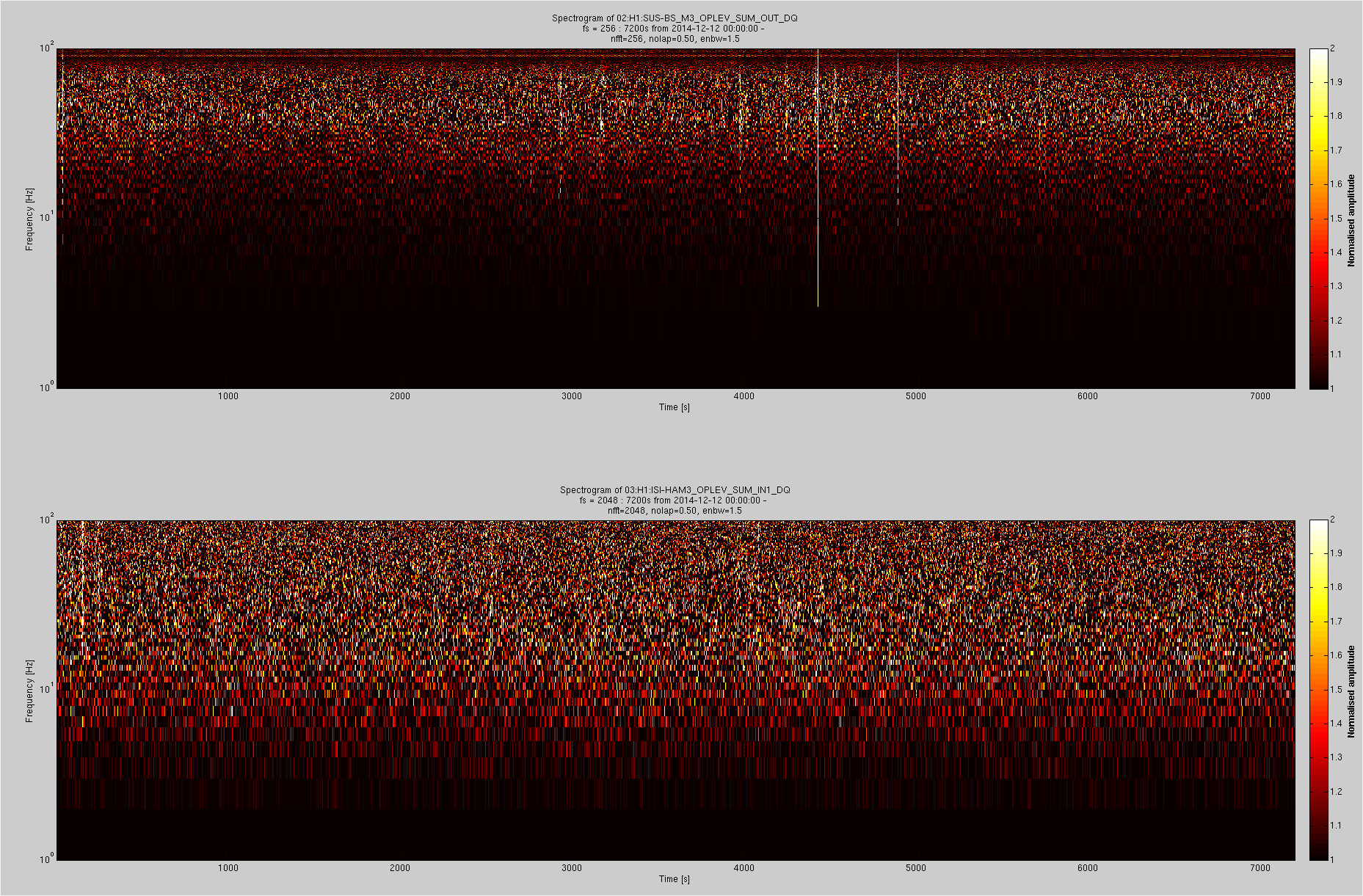
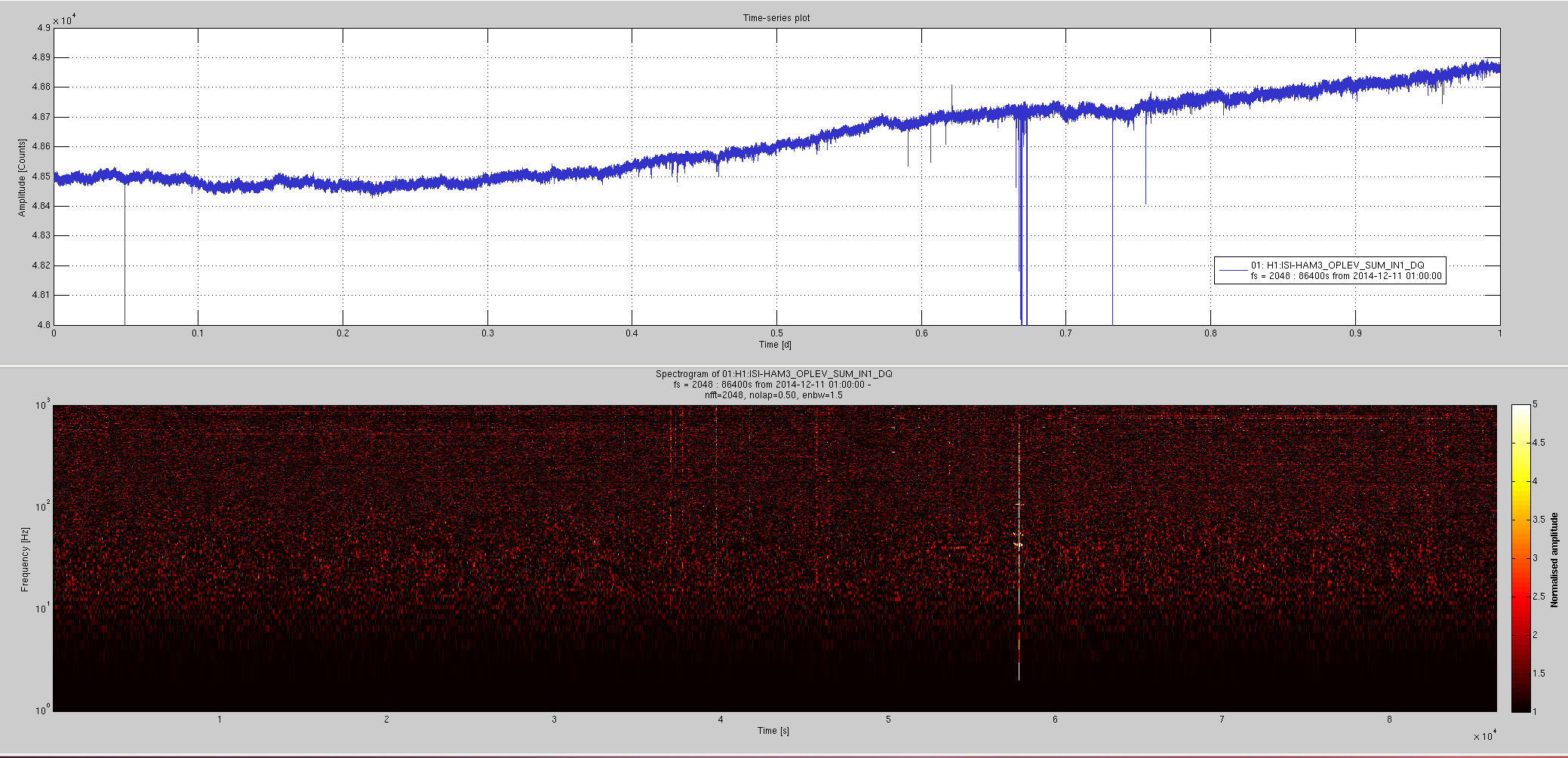
This is regarding the BS suspension damping using its oplev.
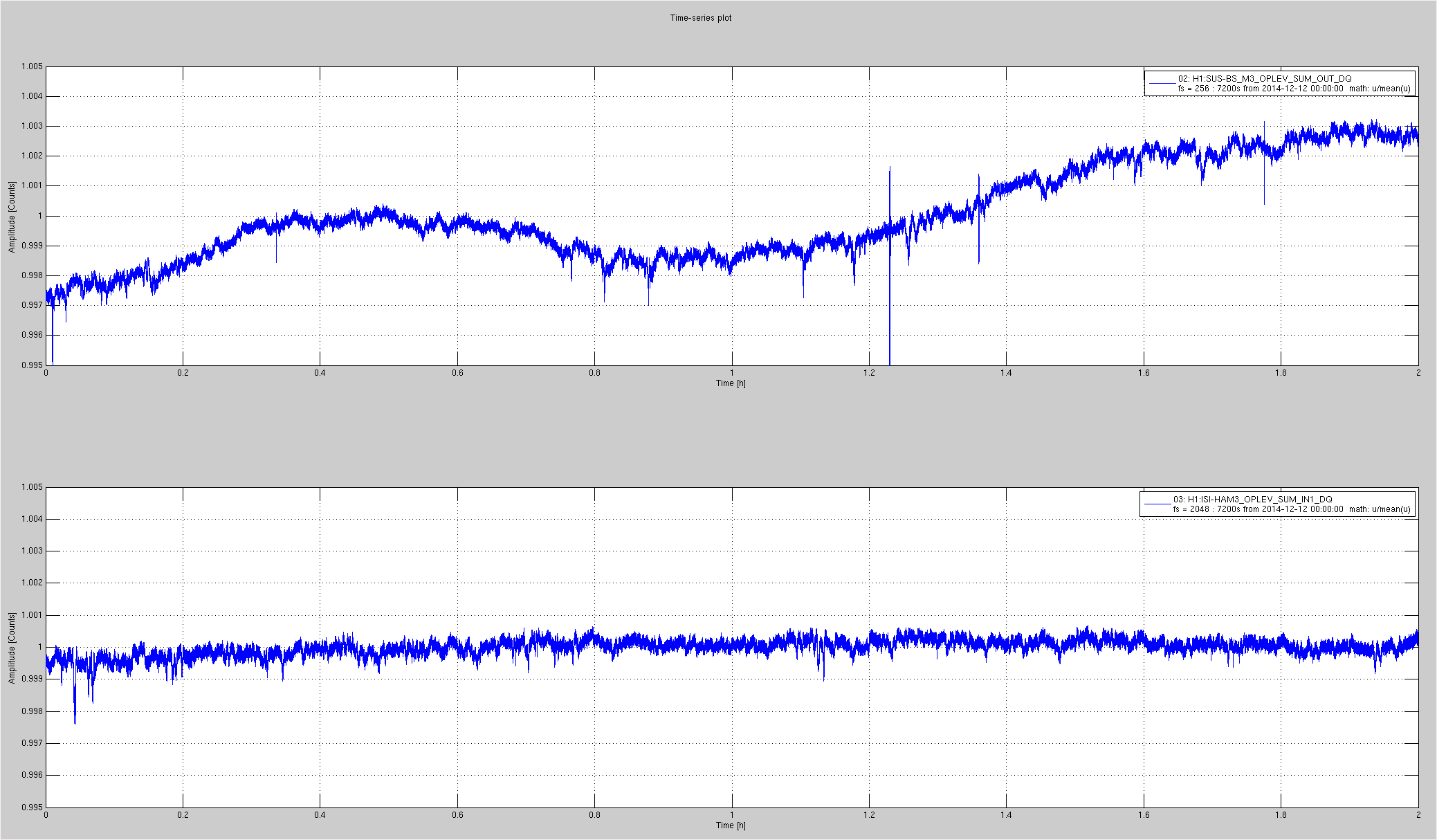
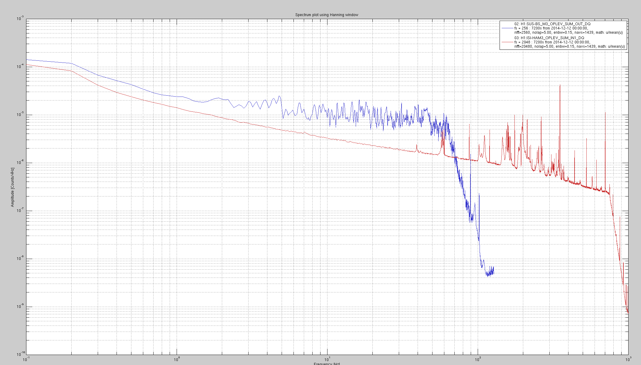
I looked at the behaviour of HAM3 and BS oplev lasers over the last two hours.
The HAM3 laser (HAM3 oplev is the preferred test bed for the lasers we fix before we plug them into core optics suspensions) has an order of magnitude lower noise in the 10 to 100Hz band. The forest of peaks we see above 100 Hz are probably from the pier motion and not from the laser itself.
I have also looked at the 24 hr trend of the HAM3 oplev. There are a few glitches during the time people were working in the LVEA. I expect these will not be present when things are quiet.
Shifting the HAM3 oplev laser to BS oplev should improve the BS suspension damping.
Jeff K, Suresh, Sheila
The wind is picking up. We are having 60 mph gusts and can hear it on the roof, so that's for interferometery tonight. High winds started at around 2:50 UTC, December 12th.
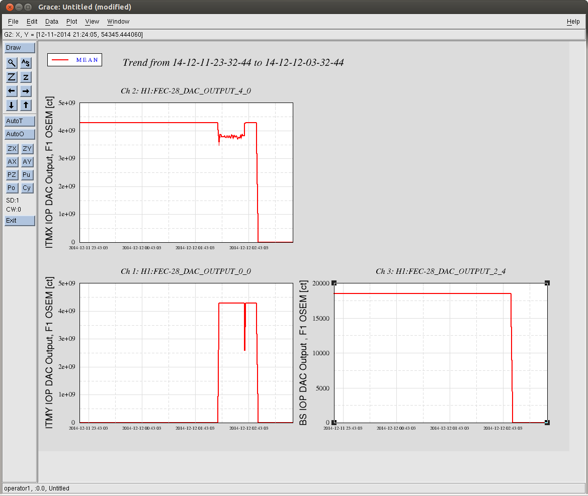
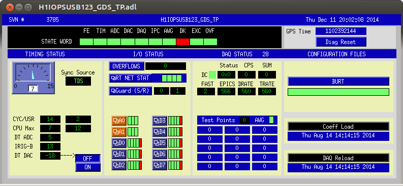
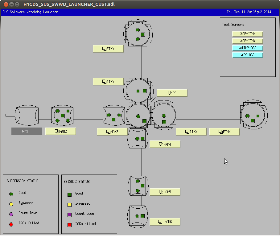
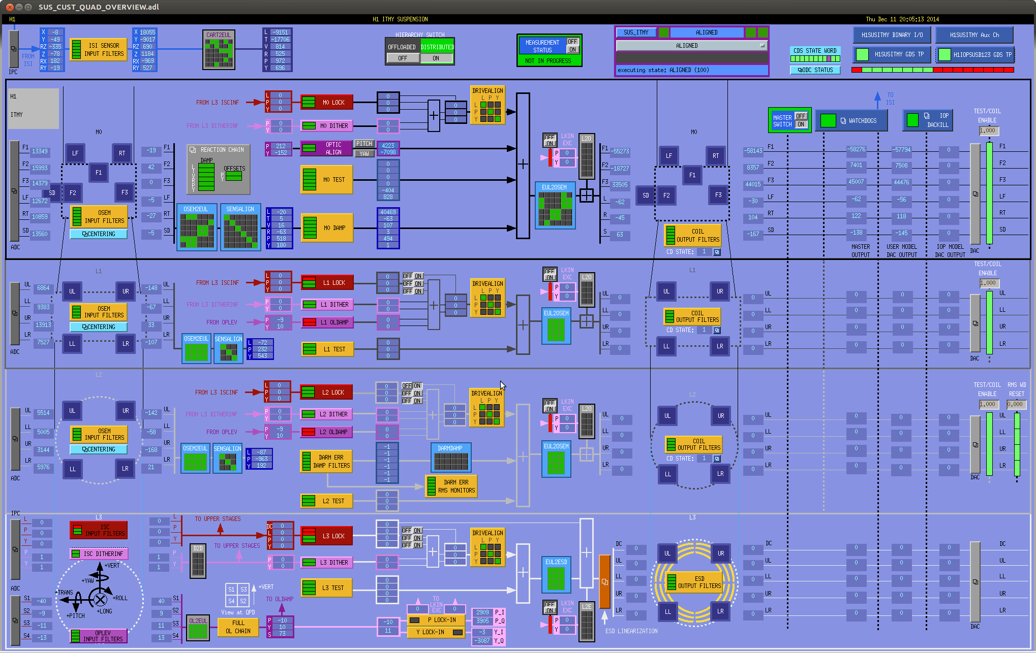
J. Kissel, S. Doravari

Hoping to take advantage of the windy night without interferometry I tried to start taking some long-needed acceptance transfer functions on the ITMs. However, I immediately discovered that the IOP outputs from the suspensions were zeroed out. Signals apparently dropped out at for all SUS on h1susb123, i.e. H1SUSITMX, H1SUSBS, and H1SUSITMY at the same time, roughly Dec 12 2014 02:52 UTC (Dec 11 2014 18:52:00 PST, GPS 1102387936 -- about when Sheila noticed that the ITM pitch motions were ~10 [urad] and started to blame the changes to SEI systems), see attached.

I checked everything I'd checked last time there were loose wires in the software  (see LHO aLOG 13329), but they didn't report any problems:
(1) All SUS watchdogs are green (2014-12-11_H1SUSITMY_Overview.png)
(2) All IOP Software Watchdogs are green (2014-12-11_SWWD_Status.png)
(3) dmesg of h1susb123 doesn't report any badness (2014-12-11_h1susb123_dmesg.txt)
(4) proc status seems happy (2014-12-11_h1susb123_procstatus.txt)

I've called Dave and left a message. I'm going to do the same sledge hammer solution we did last time and kill all USER front end processes, restart the IOP model, and restart the USER models.

I hate this -- we really need a way to reset this WD DACKILL look alive WITHOUT having to take down the entire front end...
S. Dwyer, K. Venkateswara
Sheila turned WFS on and locked the X-arm using the green laser. I then took measurements with and without the LLO sensor correction on ITMX and ETMX. I also tried out the low-frequency sensor correction (using Rich's SC filter and the tilt-subtracted sensor ), only at ETMX. ASD plots are attached showing various sensors. And a comparison of the control signal for the different configuraitons.
It is likely that ALS is not sensitive enough below 1 Hz to see the effect of the sensor correction.
I began realigning the PRC probe beam (sent into HAM2 via IOT2R) to the PRM. First of all I aligned the beam reflected from PRM and transmitted through IM4 back into the aux laser path, using an iris, centering on lenses, and the FI aperture as a guide. This required some significant repositioning of the lower IOT2R periscope mirror, because this was adjusted in order to dump the IM4 trans beam recently for the benefit of the ISS photodiode. I then turned on the aux laser and overlapped the main beam (as best as possible just by looking at the spots on a card at two locations). With the main beam now coarsely overlapped with the aux beam, I aligned it to the RFPD that is used to generate the main laser / aux laser beat signal, maximizing the DC output of the PD. I observed the RF output on the HP spectrum analyzer, but wasn't able to see a beat signal (this might require more tuning of the aux laser temperature offset). One thing I did notice, however, were big peaks in the spectrum at the 9MHz and 45MHz sideband frequencies. These peaks remained when the aux laser was turned off. Since this beam is just the forward beam from the IMC, one would hope that the RF sidebands were pure phase modulation... is this an indication of unwanted RFAM in the IMC trans beam already? I don't know for sure what the IFO state was when I observed this, though I do know that the PRM was deliberately misaligned by this time.
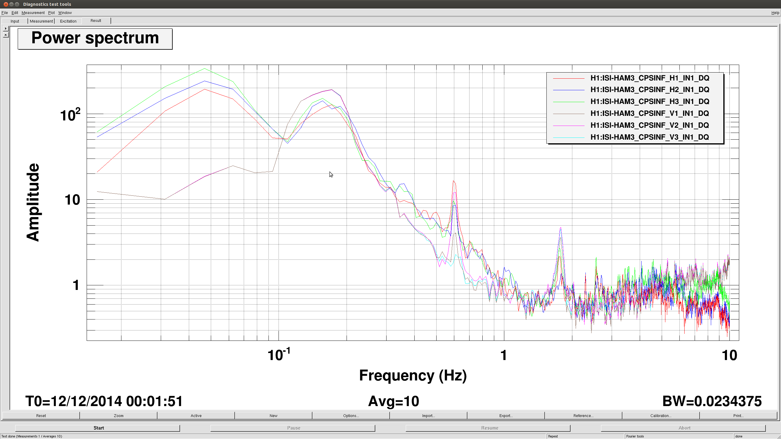
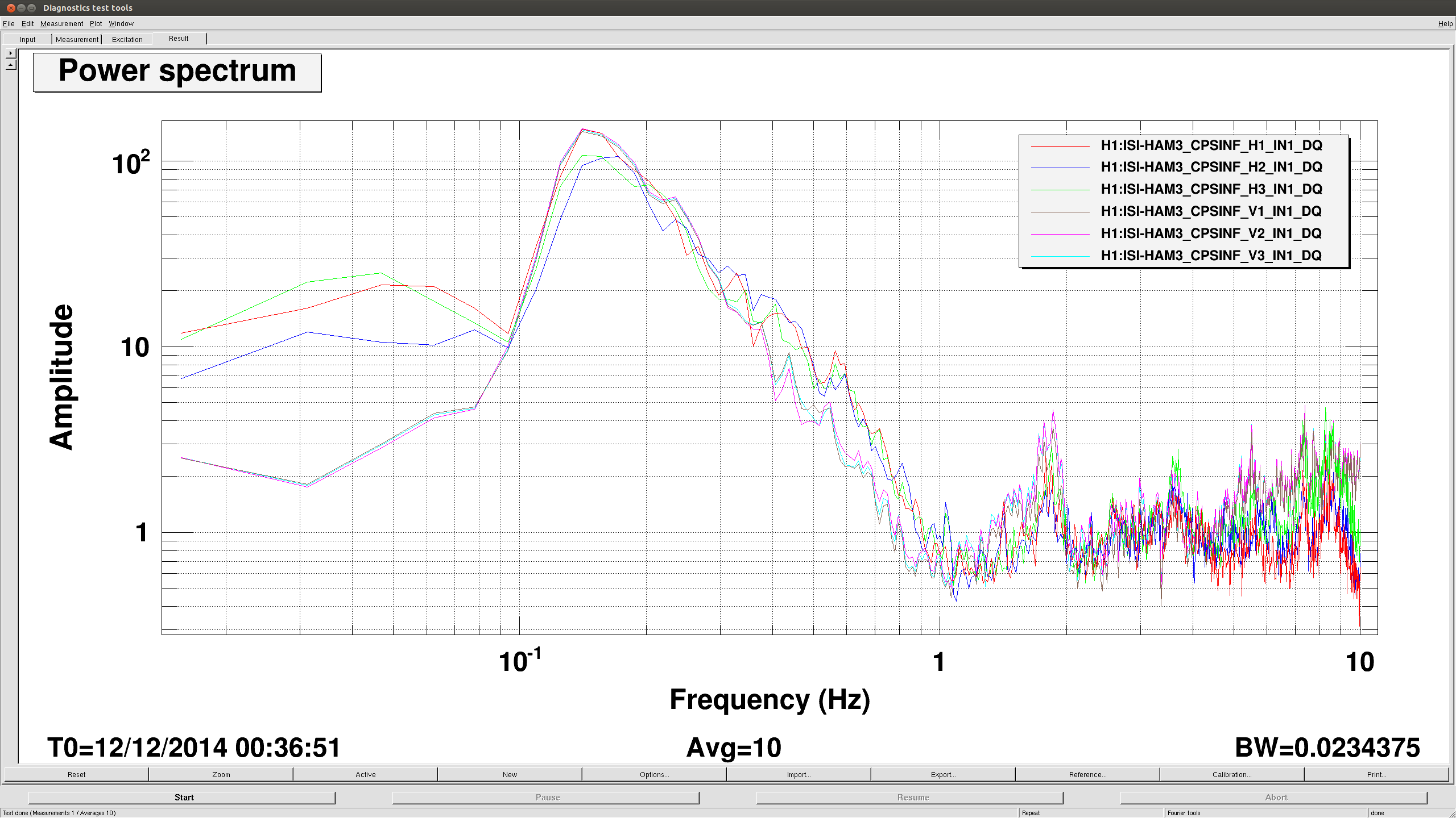
The last couple of days Krishna and I have been working on sensor correction everywhere, but have been having troubles on HAM3. This is not exactly related to that effort, but we noticed that there is a very Q-y feature in the HAM3 ISI and SUS spectra. Jeff helped me dig into this and we are pretty sure this is not due to the suspensions, but it's been there the last couple of days, with and without sensor correction. It doesn't show in HEPI or the ground spectra, so I'm not sure where this comes from. When the IMC isn't being used I will try turning isolation loops off to see if the ISI is causing it. Attached spectra is of the MC2 suspension point(ISI GS-13's), but PR2, MC2 OSEMS and ISI CPS's see this, as well.
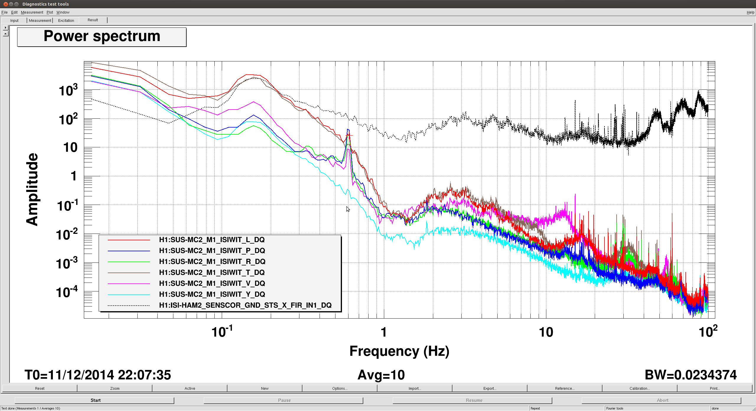
And by "pretty sure" it's not the SUS, Jim means "it's definitely not." The first HSTS modes are at 0.67 [Hz], and the recent design study (see G1401291) have revealed that even with crappy legacy damping filters and gains that are still in place, the Qs of all the modes are reduced well below what's seen here.

Also of note -- The 0.6 [Hz], and 1.5, and 2.9 [Hz] features are seen in IMCL, PRCL, and the HAM Optical lever, so it's definitely the ISI, because it's common to both SUS in the chamber and their moving mass doesn't couple well enough to the ISI to move the thing in all DOFs like is shown here.
And now you don't!
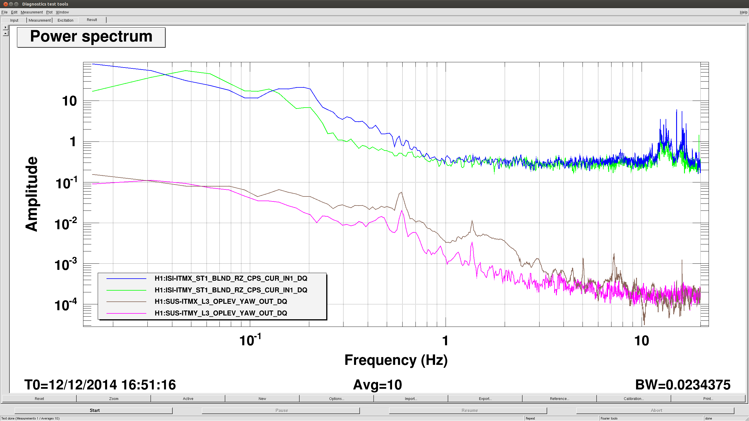
I started looking for the .6hz whatsits and it's gone now. The local sensors didn't see it when I looked this morning, but looking back in time it disappeared some time between 16:00 (first plot) and 16:30 (second) yesterday. We are also seeing something similar on the ITMs' oplevs (third plot, you can see it in Krishna's post about Xarm sensor correction, too) now as well, so whoever fixed HAM3 should keep going.
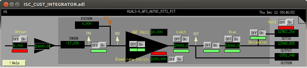
A new type of filter block is now available in the real-time system. The Integrator Filter Module (IFM) implements a single integrator only, but has a couple of additional features compared to a standard filter module:
The attached screen shot represents the new IFM. The available parameters are
The testpoint and EPICS channel names are the same as in the standard filter module:
The SFM uses a bit encoded momentary switch for its enables. However, this requires state notation code support; and the IFM uses individual EPICS bi channels.
/*  This is an integrator with output limiter and bleed off
    Inputs:
    1. Error signal (double)
    2. Excitation input (double)
    3. Request word (bit encoded int)
    -----------------------------------------------------------------------
    Bit     Name            Description
    -----------------------------------------------------------------------
     0      Filter          Request for integrator to run
     1      Input Switch    Request for input switch to be on
     2      Offset Switch   Request for offset to be enabled
     3      Limit Switch    Request for the limit switch to be engaged
     4      Output Switch   Request for the ouptut switch to be on
     5      Hold Output     Request for the output to hold
     6      Bleed Enable    Request for filter to bleed off
     7      Bias Enable     Request for output bias to be on
    15      Decimation      Request for output decimation (8Hz single pole)
    -----------------------------------------------------------------------
    4. Offset input (double)
    5. Gain input (double)
    6. Unity gain frequency in Hz (double)
    7. Bleed rate in cts/s (double)
    8. Maximum absolute value/limiter (double)
    9. Bias input (double)
   10. Model rate in Hz (double)
   Outputs:
    1. Control signal (double)
    2. IN1 ouptut (double)
    3. IN2 output (double)
    4. OUT ouptut (double)
    5. Decimated control signal (double)
    6. Status word (bit encoded int)
    -----------------------------------------------------------------------
    Bit     Name            Description
    -----------------------------------------------------------------------
     0      Coeff Reset     not used.
     1      Master Reset    Momentary; when set, INT will reset all
                            filter history buffers.
     2      Input On/Off    Enables/disables signal input to INT.
     3      Offset Switch   Enables/disables application of INT input
                            offset value.
     4      Filter Request  Set to one when an INT filter is requested ON,
                            or zero when INT filter requested OFF
     5      Filter Status   Set to one by INT when an INT filter is ON,
                            or zero when INT filter is OFF
     6      Limiter Switch  Enables/disables application of INT output
                            limit value.
     7      Limiter Status  Set for 1 sec, when the limiter is enabled
                            and the output value became too large.
     8      Decimation      Enables/Disables application of decimation
            Switch          filter to INT OUT16 calculation.
     9      Output Switch   Enables/Disables INT output (INT OUT and
                            OUT16 variables)
    10      Hold Output     If (!bit 26 && bit27), INT OUT will be held
                            at last value.
    11      Bleed Enable    If set, the accumulated integrator value will
                            be bled off with the specifed bleed rate
    12      Bias Enable     If set, a bias will be added to the output
    -----------------------------------------------------------------------
*/

#define INTFILTER 0x01
#define INTINPUT 0x02
#define INTOFFSET 0x04
#define INTLIMIT 0x08
#define INTOUTPUT 0x10
#define INTHOLD 0x20
#define INTBLEED 0x40
#define INTBIAS 0x80
#define INTDEC 0x8000

#define PI 3.1415926535897932384626433832795028841971693993751058

#ifdef _WIN32
typedef enum {false, true} bool;
#define isnan(s) 0
#define printk(s)
#endif

bool myfinite (double s)
{
    // By IEEE 754 rule, 2*Inf equals Inf
    return !isnan(s) && ((s == 0) || (s != 2*s));
}

void Integrator (double* in, int ins, double* out, int outs)
{
    /* INPUT and OUTPUT vars for Integrator function block */
    double inval = 0.0;
    double exc = 0.0;
    int req = 0;
    double ofs = 0.0;
    double gain = 0.0;
    double ugf = 0.0;
    double bleed = 0.0;
    double limit = 0.0;
    double bias = 0.0;
    double rate = 16384;

    double outval = 0.0;
    double in1 = 0.0;
    double in2 = 0.0;
    double out1 = 0.0;
    static double out16 = 0.0;
    int stat = 0;

    /* local vars */
    static int error = 0;
    static double oldout = 0.0;
    static double holdval = 0.0;
    static int limcount = 0;
    double val = 0.0;
    double g = 0.0;

    /* argument check */
    if ((ins != 10) || (outs != 6)) {
        if (!(error & 0x1)) {
            printk("Integrator: wrong number of inputs and/or outputs\n");
            error |= 0x1;
        }
        return;
    }

    // Read input values
    inval = myfinite (in[0]) ? in[0] : 0.0; // must be finite
    exc = myfinite (in[1]) ? in[1] : 0.0; // must be finite
    req = (int) (myfinite (in[2]) ? in[2] : 0); // must be finite
    ofs = myfinite (in[3]) ? in[3] : 0.0; // must be finite
    gain = myfinite (in[4]) ? in[4] : 0.0; // must be finite
    ugf = myfinite (in[5]) && (in[5] > 0) ? in[5] : 0.0; // must be finite and non-negative
    bleed = myfinite (in[6]) && (in[6] > 0) ? in[6] : 0.0; // must be finite and non-negative
    limit = myfinite (in[7]) ? (in[7] > 0 ? in[7] : -in[7]) : 0.0; // must be finite, take abs
    bias = myfinite (in[8]) ? in[8] : 0.0; // must be finite
    rate = (in[9] >= 0) ? in[9] : 1.0; // must be finite and positive

    // Add offset and muliply with gain
    val = inval;
    if (req & INTOFFSET) {
        val += ofs;
    }
    val *= gain;
    // input switch and input test points
    in1 = val;
    if (!(req & INTINPUT)) {
        val = 0.0;
    }
    val += exc;
    in2 = val;

    // Calculate filter
    if (req & INTFILTER) { // filter on
        g = 2*ugf/rate;
        if (g > 1) { // ugf above Nyquist!
            g = 1.0;
        }
        oldout = oldout+PI*g*val;
    }
    else { // filter is off
        oldout = val;
    }
    // enforce limits when on
    if (req & INTLIMIT) {
        if (oldout < -limit) { // lower limit exceeded
            oldout = -limit;
            limcount = (int)rate + 1;
        }
        else if (oldout > limit) { // upper limit exceeded
            oldout = limit;
            limcount = (int)rate + 1;
        }
    }
    if (limcount > 0) {
        --limcount;
    }

    // Bleed off integrator value if selected
    if (req & INTBLEED) {
        g = bleed/rate;
        if (oldout > g) {
            oldout -= g;
        }
        else if (oldout < -g) {
            oldout += g;
        }
        else {
            oldout = 0.0;
        }
    }

    // Output testpoint
    out1 = oldout;

    // Output enabled
    if (req & INTOUTPUT) {
        val = oldout;
    }
    else {
        val = 0.0;
    }

    // Add bias if selected
    if (req & INTBIAS) {
        val += bias;
    }

    // Hold output if selected
    if (req & INTHOLD) {
        outval = holdval;
    }
    else { // no hold
        outval = val;
        holdval = val;
    }

    // Compute decimated output: 8Hz single pole low pass
    if (req & INTDEC) {
        g = 2*8.0/rate;
        if (g > 1) {
            g = 1.0;
        }
        g *= PI;
        out16 = (1-g)*out16+g*outval;
    }
    else { // no decimation
        out16 = outval;
    }

    // Set status
    stat = 0;
    stat |= (req & INTINPUT) ? 0x0004 : 0;
    stat |= (req & INTOFFSET) ? 0x0008 : 0;
    stat |= (req & INTFILTER) ? 0x0010 : 0;
    stat |= (req & INTFILTER) ? 0x0020 : 0;
    stat |= (req & INTLIMIT) ? 0x0040 : 0;
    stat |= limcount ? 0x0080 : 0;
    stat |= (req & INTDEC) ? 0x0100 : 0;
    stat |= (req & INTOUTPUT) ? 0x0200 : 0;
    stat |= (req & INTHOLD) ? 0x0400 : 0;
    stat |= (req & INTBLEED) ? 0x0800 : 0;
    stat |= (req & INTBIAS) ? 0x1000 : 0;

    // Write output values
    out[0] = outval;
    out[1] = in1;
    out[2] = in2;
    out[3] = out1;
    out[4] = out16;
    out[5] = stat;
}
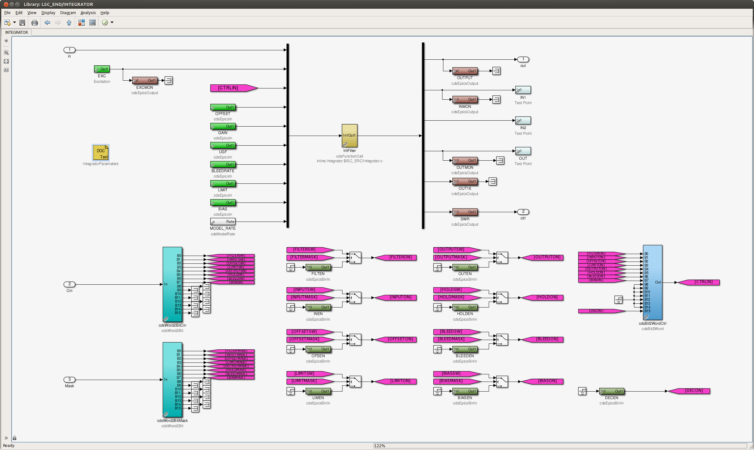
Here is the corresponding simulink block.
Initial attempts to take undamped TFs on ITMX & ITMY exhibited rung up P & R modes (see LHO aLOG entry 14653). For the next attempt, fine tuning of excitation amplitudes was necessary to avoid ringing up these modes.

Phase 3b (in-vacuum) undamped TF measurements have been taken for ITMX & ITMY (QUAD) suspensions as follows:-

- ITMX M0-M0 undamped results (2014-10-30_0700_H1SUSITMX_M0_ALL_TFs.pdf)
- ITMX R0-R0 undamped results (2014-10-30_0700_H1SUSITMX_R0_ALL_TFs.pdf)
- ITMY M0-M0 undamped results (2014-10-28_1200_H1SUSITMY_M0_ALL_TFs.pdf)
- ITMY R0-R0 undamped results (2014-10-28_1200_H1SUSITMY_R0_ALL_TFs.pdf)

ISI Status: ISI's damped and FULLY_ISOLATED via Guardian.

ITMX & ITMY undamped TFs above have been compared with other similar QUADs at the same phase of testing (allquads_2014-10-30_AllQUADS_Doff_Phase3b_ALL_ZOOMED_TFs.pdf). The plot key is as follows:-

Blue Trace = Model Prediction (fiber/thincp).
Orange Trace = L1 ITMX (fiber 2013−09−04), Phase 3b.
Black Trace = L1 ITMY (fiber 2013−09−05), Phase 3b.
Magenta Trace = H1 ITMY (fiber 2014−10−28), Phase 3b.
Cyan Trace = H1 ITMX (fiber 2014−10−30), Phase 3b.

Summary:

M0-M0, main chain TFs are a very good fit to the model, for all DOFs, with only some minor cross-couplings from P2V.

R0-R0, reaction chain TFs agree with the model predictions and are consistent with similar QUADs. The largest deviation from the model can be seen with the ~1.45 Hz P mode, a consequence of the harness routing stiffening the suspension, seen before. Some minor cross-couplings are also present: from P2L, P2R, and P2V only for ITMY. Damped TFs should be taken to verify that damping loops suppress these cross-couplings.

All data, scripts and plots have been committed to the sus svn as of this entry.
Power spectra had been taken and processed a while back, but not posted until now. These power spectra measurements have been compared to previous Phase 3 measurements for H1 ITMs (allquads_2014-11-26_Phase3_H1ITMX_ALL_Spectra_D*.pdf). The plot key is as follows:-

Black Dashed Line = Expected Sensor Noise
Blue Trace = H1SUSITMY 2013−07−19_1400, Phase 3b (in-vacuum)
Green Trace = H1SUSITMX 2014−04−11_1600, Phase 3b (in-vacuum)
Red Trace = H1SUSITMX 2014−07−07_1000, Phase 3a (in-air)

Summary:

Noise floors for recent ITMX measurements are consistent with previous measurements, but are much more noisy below 40 Hz due to air turbulence, clean rooms, purge air etc. Oddly, L1 and L2 OSEM DOFs appear to suffer from a scaling problem. However, scaling is correct for L1 & L2 EULER DOFs. n.b. the same discrepancy was also observed in the data taken before the optic was swapped. Thus, raising no concerns.

All data, scripts and plots have been committed to the sus svn as of this entry.
Damped transfer functions can be found in LHO aLOG 15575.

