Since we rolled out the sensor chains from our investigation (I'll do a summary alog about that in a minute), I've looked at the actuation chain.
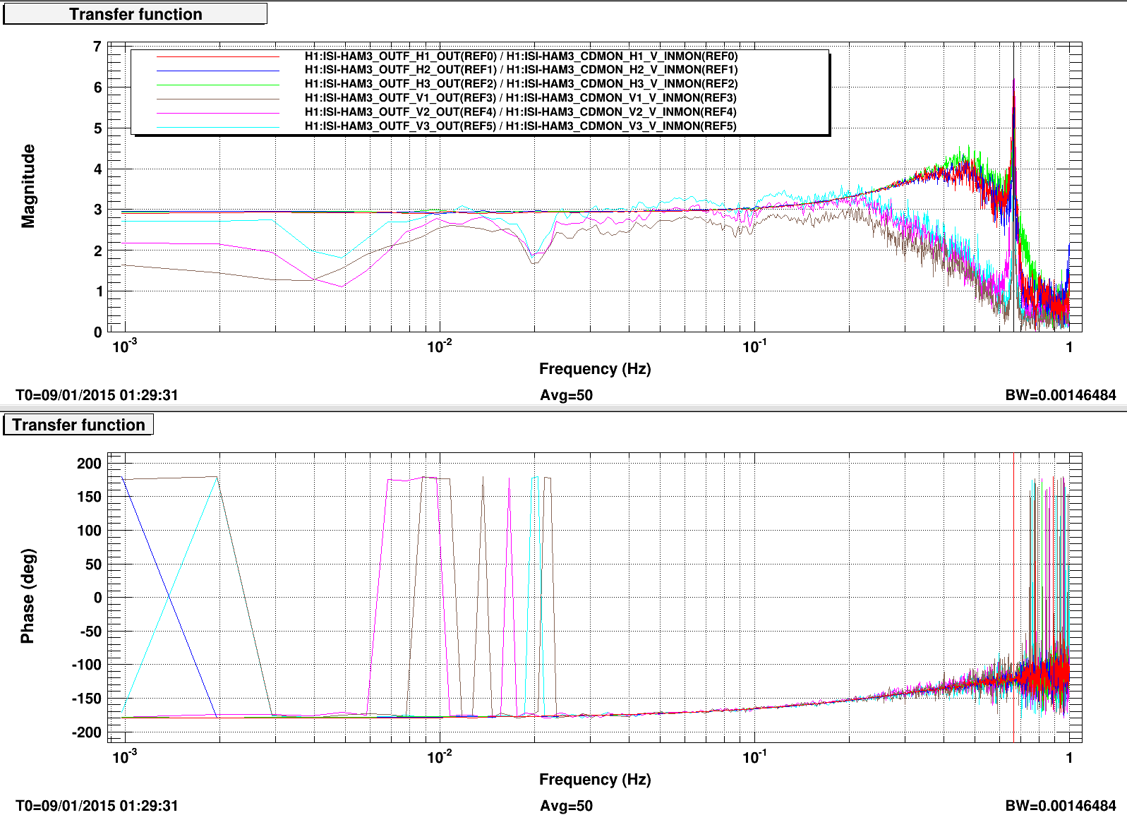
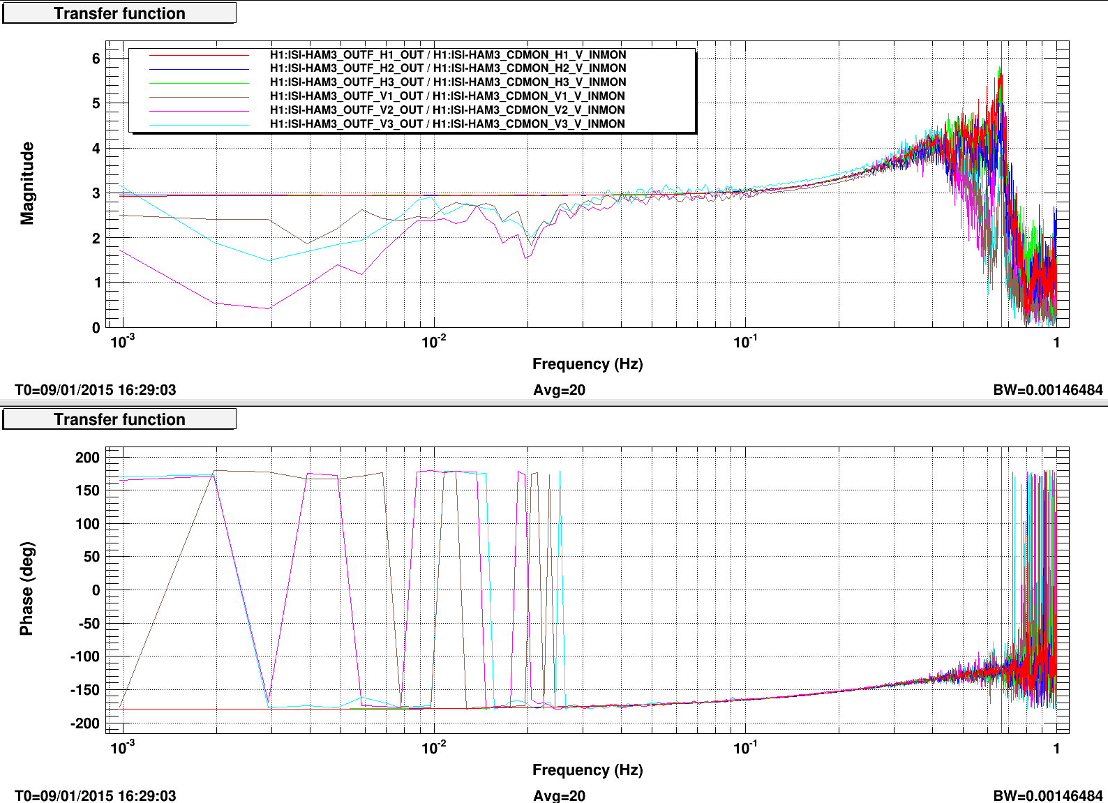
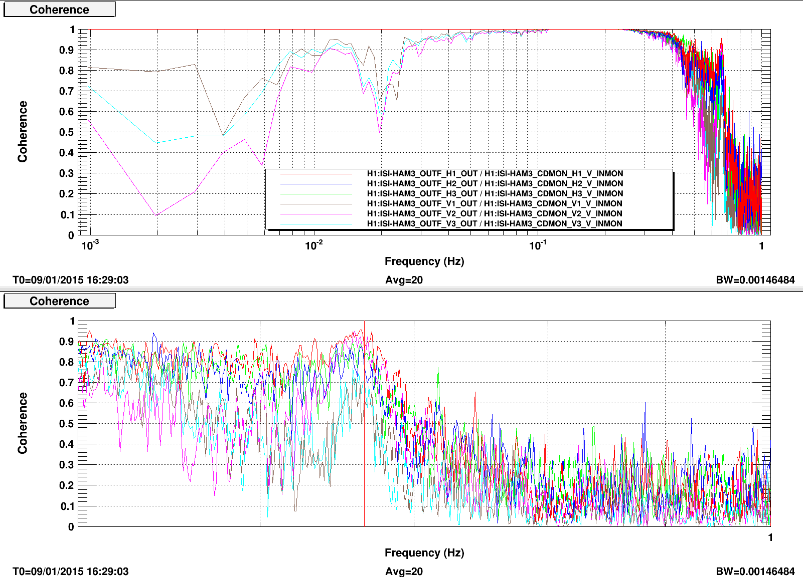
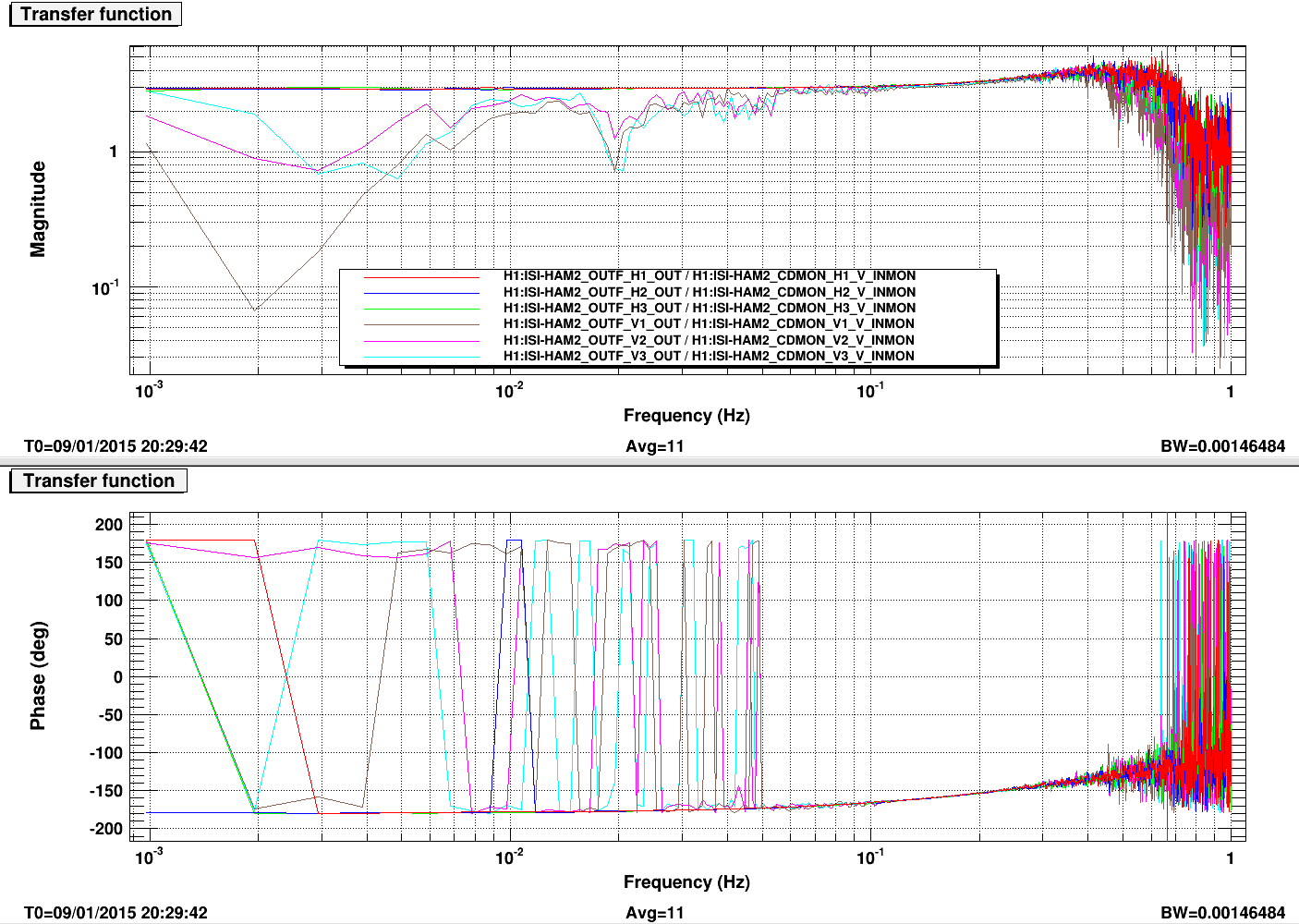
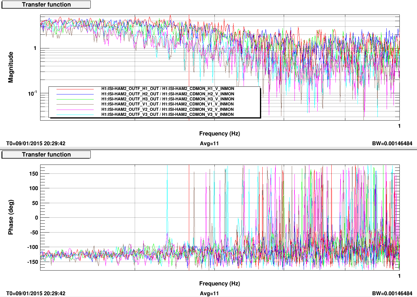
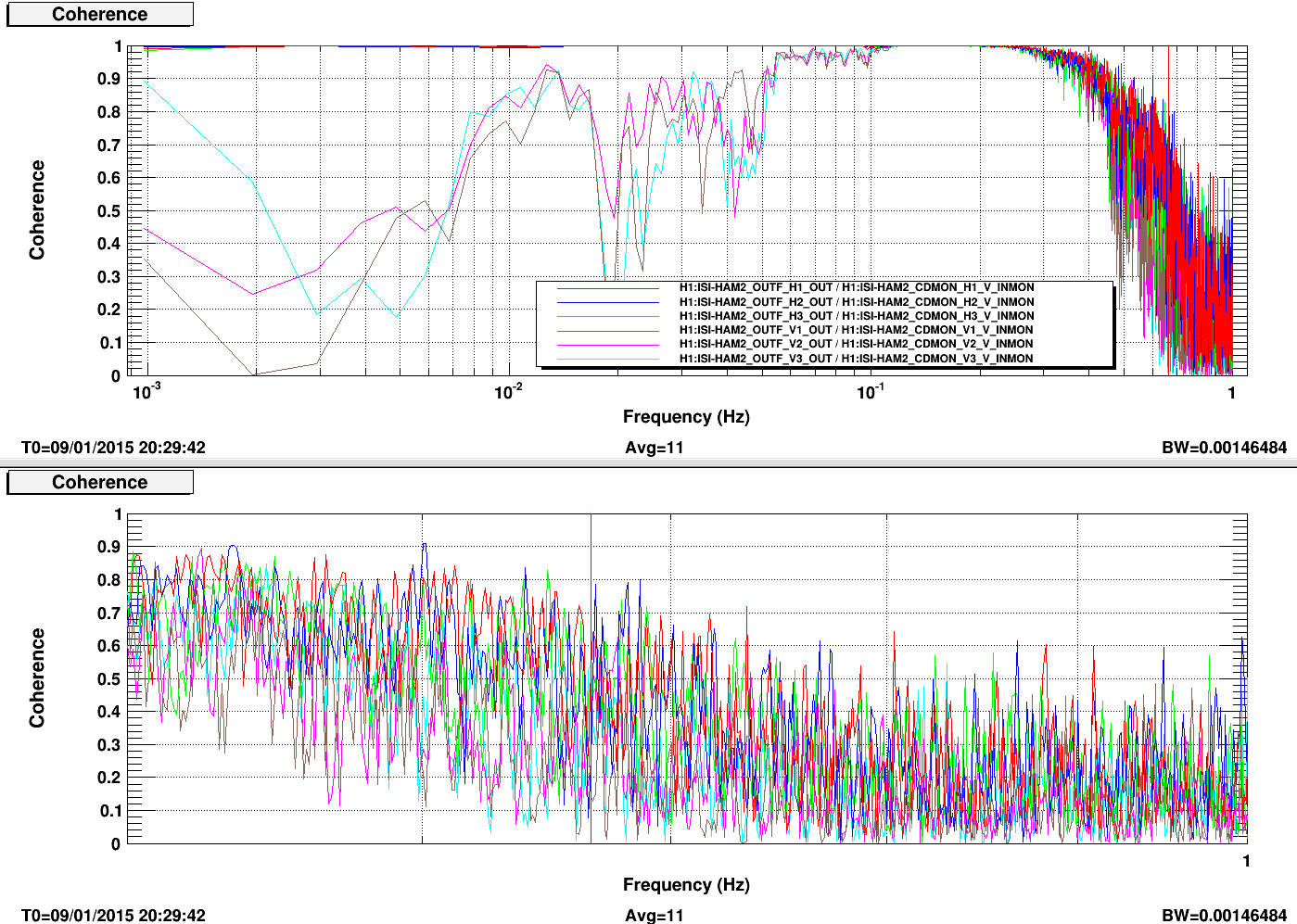
I took the transfer function between the actual ouput of the actuators (counts) and the related voltage read by the coil driver readback channels. This is the same information in different units, so except some color coming from the electronics, we shouldn't see any sharp peak in the transfer function. I did this exercise on HAM3 (HEPI Z sensor correction ON and OFF) and HAM2 (Sensor correction OFF) for the comparison.
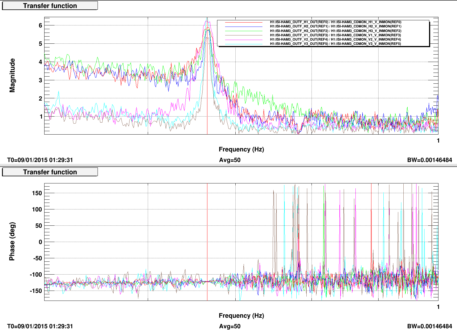
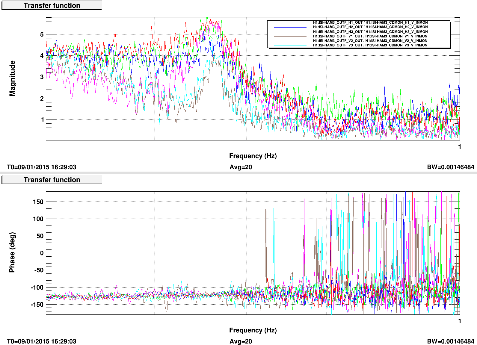
The results are interesting. First I'm not sure I understand why we don't have a perfect coherence (noise?), but I don't think that's linked to our issue. More interesting, we can see a small peak around 0.66Hz on HAM3 when the sensor correction is OFF (which is not the case on HAM2).
This might be an indication that the problem is coming from the actuators.