betsy.weaver@LIGO.ORG - posted 10:41, Tuesday 06 January 2015 (15888)
TMSy and ETMy in SAFE mode
Due to Dave's ADC reboots at EY, I've taken the TMSy and ETMy guardian states from ALIGNED to SAFE.
Due to Dave's ADC reboots at EY, I've taken the TMSy and ETMy guardian states from ALIGNED to SAFE.
Turbo rotor left elevated for now
I've lowered the temperature setpoint for the XEND VEA back to 65F (down from 67). In order to do so I have turned off the single stage of heat. We'll probably see some overshoot.
no restarts reported.
Actually this is for the past two weeks.

The variation in the frontend laser's pump diode output power coincides with a dip in the relative humidity
in the diode room.  Not surprisingly the relative humidity change is also indicated by the sensor inside the
high power oscillator.  If this signal was used as an alarm, which was intended to detect the suspicion of
a water leak, the laser would have been automatically shut down.

Everything else looks nominal with the only exception being related to the site-wide power glitch.
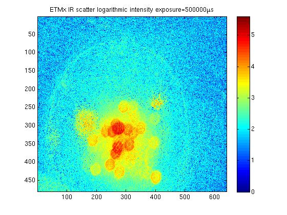
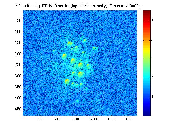
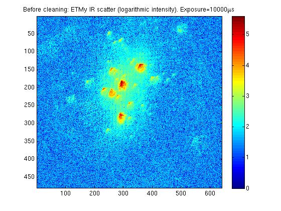
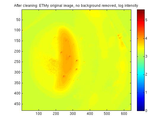
Attached are some comparison images of ETMy before and after it was cleaned just before Christmas. I have also attached a pitcure or ETMx before it was cleaned, although it is taken at a much longer exposure and is not as well focused making direct comparision of images difficult. The three very bright spots which were previously visable on the ETM are no longer visible, these would have been the three macroscopic pieces of first contact which were removed from the mirror.
Imaging method:
The camera position is identical in the before and after images. For all pictures, an image is taken with the test mass is illuminated with IR locked in the arm. The trans mon is misaligned so there is minimal green light present. A background image is taken with no IR (ITM misaligned), and this is subtracted from the original image to produce the final image. The analogue gain is set to 100, a 12 bit image is taken, and each image is made of 100 averages. The exposure of the ETMx images is 10000micoseconds, and ETMx is taken at 500000 microseconds.
BRDF calculation:
Done using the same method as alog15633, with calibration factor 1.6x10⁻¹⁰ (µs)(W)/count (same as before). The incident power is calculated by averaging ASC-TR_A_SUM_OUTPUT and ASC-TR_B_SUM_OUTPUT as outlined by Dan in alog 15431.
| OPTIC | Date taken | Incident power (W) | Power scattered onto photodoide (W) | BRDF |
| ETMy | 10 December 2014 | 18W | 8.4e-7 | 0.023 |
| ETMy | 5 January 2015 | 21W | 1.16e-7 | 0.004 |
| ETMx | 11 December 2014 | 45W | 8e-8 | 0.001 |
ETMy shows a factor of ~6 improvement since being cleaned, but it still doesn't look as good as ETMx. I will see if I can focus the camera better on ETMx to get a nicer comparison.
J. Kissel, B. Shapiro
The summary says most of it -- we've confirmed with two degrees of freedom of top to top transfer functions. Our best candidate is that the temperature in the VEA is too high. I tried adding a vertical offset in either direction, in hopes that we have enough range to recover the drooping, but it appears we do not. We'll first try restoring the XVEA temperature (if not surpassing it), but we may have to vent again. Cross your fingers.
Details:
Hoping that we could test the newly turned on H1 SUS ETMX ESD for functionailty, Brett and I noticed the optical lever did not appear centered in either the misaligned or aligned state. We could only restore the optical lever centering by putting the alignment offsets at
P Y
Force Realignment +21.3 -122.9
Original Aligned +417.0 77.2
Change +395.7 200.1
Further, I noticed that a P request would cause both P and Y motion, and vice versa.
Betsy then trended the temperature in the VEA, see LHO aLOG 15877, and found it ~2 [deg F] or ~1 [deg C], which corresponds to about 100 [um] sag at the TOP mass (see T1400749, specifically LLO aLOG 15636. I note that this is at the TOP mass, because the lower stages will sag MORE, since there are cascading vertical blade springs.
We then, in the interest of time, took the transfer functions we know are the most sensitive to rubbing: P to P and V to V. These transfer functions are attached, for the various vertical offsets applied; see 2015-01-05_2358_H1SUSETMX_M0_Mono_WhiteNoise_*_0p01to50Hz.pdf. The vertical offsets were +/- 200 000 [ct], equivalent to most of the DAC range, which is roughly +/-115 [um_pk]. We can clearly see that the first several modes have shifted significantly, and several DOFs are cross-coupled in. Notable, however, is the highest-frequency modes are unaffected. This implies that the top-mass is free, and the lower masses are restricted, as seen in a QUAD's mode shapes. This makes sense, because for this most recent cleaning (see LHO aLOG 15744), the *only* activity in chamber was to clamp the test mass briefly for cleaning. Further, sadly, even with 100+ [um] of displacement in vertical, we could not move the the suspension free.
Note, we checked the reaction chain with P and V TFs, and it appears free and clear (see 2015-01-06_0152_H1SUSETMX_R0_WhiteNoise.pdf). We did not check the TMS, since it was not touched.
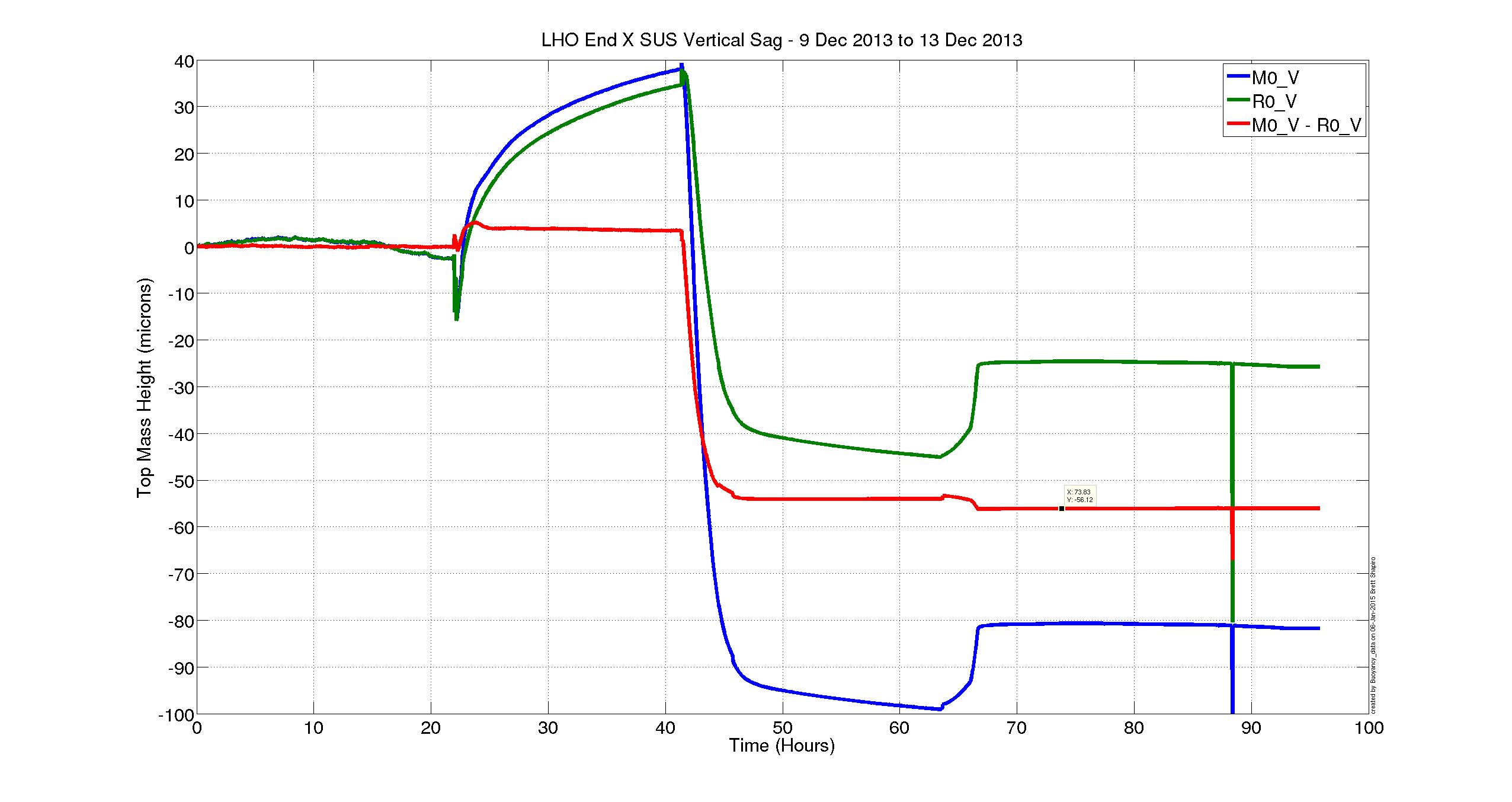
Finally, because we were amazed that the SUS had sagged more that 100 [um], and that we know that Betsy set the EQ stops when the VEA was at ~70 [deg C], Brett compared the top-mass displacement of the main chain, reaction chain, and TMS to gauge the amount of displacement compared to the other SUS in the chamber, which should have roughly comparable sag because they've the same blade springs and overall suspended mass (roughly). We attach two trends, EX_SAG_21DecTo5Jan.png (a 15 day trend that includes the pump down) and EX_SAG_22DecTo5Jan.jpg (a 14 day trend to zoom in on the long term temperature equilibration). From the 21st, one can see that the removal of air [the first big sharp drop], caused all SUS to drop. However, the main chain is expected to drop 170 [um] (see T1100616), and the reaction is expected to drop 100 [um]. While the reaction chain drops as expected, the main chain only drops ~125 [um], indicating a sort of bottoming out. Further, from the 22nd's trend, we see the temperature dependence is different (the bias has been removed for clarity).
So, again. Bad news. Hopefully we can pull this SUS back up with temperature!


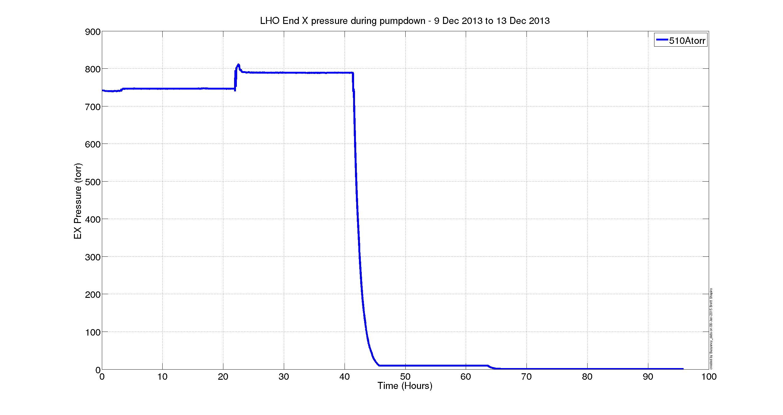
Regarding the expected buoyancy shift during pumpdown, the test masses do not seem to sag as much as expected during the pump down. Attached are plots of previous ETMx, ETMy, and ITMx pumpdowns (circa 2013 and 2014), showing this.
In summary, according to the T1100616 buoyancy calculation sited above, the test masses should sag by ~170 um, however the plots show sags of ~120 +/- ~10 um based on where you think the suspension starts and settles to. Note, the ETMx data from Dec 2013 looks a bit suspicious and I may have chosen incorrect baselines for where the suspension was sitting in vertical height before and after pump down. It is difficult to decouple the various pumping operations and temperature effects from these plots.
QUAD Main Chain Vertical shift data taken from the plots:
ITMx 115--5= 120um
ITMy 180-65 = 115um
ETMx 150-65 = 85
ETMy 215-95 = 120

To take a closer look at the buoyancy effect during pumpdown, I removed the effect of temperature by subtracting the reaction chain vertical height from the main chain in the ETMX data Betsy posted above. The two chains should respond nearly the same way to temperature. However, they will respond differently to air pressure since they have different buoyancies (lower stages are different materials, e.g. glass vs steel at PUM).
T1100616 says the main chain should sag by 170 microns while an ERM top mass should sag 100 microns wh8ile pumping down. So if we subtract the reaction chain vertical height from the main chain vertical height during a pumpdown we should see a drop of 70 microns. The attached figure shows that the relative sag in red was only 56 microns, 80% of the prediction. The temperature effects look well suppressed since during times of constant pressure (shown in 2nd figure) the differential hieght remains constant while the individual chains are drifting significantly.
So, clearly the predicted buoyancies are not dead on. If we assume the 80% correction on the differetial sag between chains is valid for each individual chain (which may not be true), then the expected top mass sags will be
main chain: 0.8*170 = 136 microns
ERM reaction chain: 0.8*100 = 80 mircrons
CP reaction chain: 0.8*90 = 72 microns
This brings the main chain prediction much closer to Betsy's measurements above, though it is still a bit higher.
The script that generates the MATLAB figure is
.../SusSVN/sus/trunk/QUAD/H1/ETMX/Common/Scripts/Buoyancy_data.m
Sheila, Thomas, Elli, Evan
We locked the Y arm in IR, and then turned on WFS loops which feed back to IM4 and PR2 in order to keep the buildup in the arm maximized. We measured the dc counts on ASAIR_A_LF. Then we unlocked the arm and measured ASAIR_A_LF again. The results are as follows:
Using the formula in LHO#15470, the locked and unlocked values of ASAIR give an equivalent loss of 267(31) ppm on ETMY.
To account for the power in the sidebands, we use the modulation depths given in LHO#15674: Γ9 = 0.219(12) and Γ45 = 0.277(16). Then the power in the sidebands is PSB = Poff × (Γ92+Γ452)/2 = 81(7) ct. Then using our new value for the power fraction, A2 = (Pon − PSB)/(Poff − PSB), we get an equivalent loss of 286(33) ppm on ETMY, not accounting for mode mismatch.
We also took loss scans by moving spot on ETMY in a spiral pattern, as in LHO#15476. The sideband power is subtracted here as well. It appears that judicious alignment of the arm may give us lower loss (something like 140 ppm), compared to the number reported above.
In the attached plot, I've masked out data points for which the transmitted power was below 11 ct.
As before, the zero point of the displacement is somewhat arbitrary; we performed the usual initial alignment sequence for the arm (baffle PDs for TMS and the ITM, then maximize the buildup of the green power), but didn't attempt to determine the location of the spots on the test masses.
Also note that for the formula in LHO#15470, the physically meaningful solution requires us to take the negative branch of the square root when computing A (so substitute A → −A in this formula).
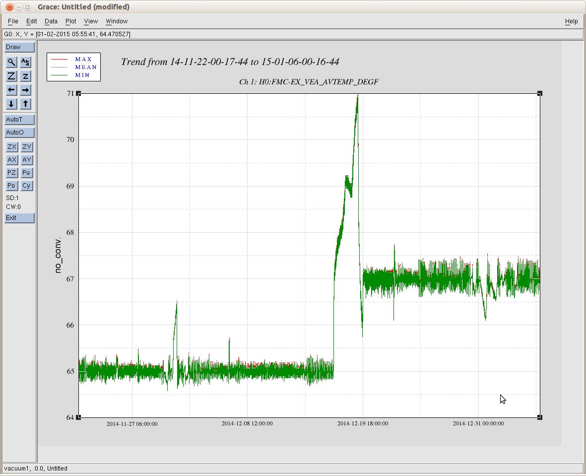
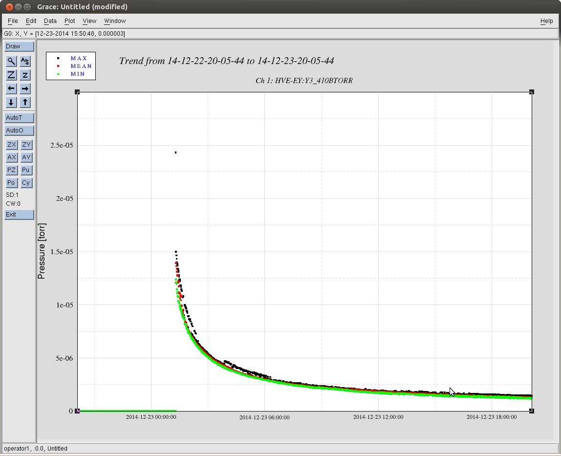
FYI, here is a 45 day Temperature trend of the End-X VEA. Note, the temperature of the VEA ran away during our vent to clean the ETMx test mass likely due to the energized cleanrooms. However, the Ex station is 2 deg hotter than it was before the vent. That said, we probably set the EQ stops during the heat spike of ~70 deg C...
R Savage, P King, J Bartlett, Ed Merilh
This morning we went into the PSL to make some adjustments. The reference cavity transmission was down by quite a lot (~1.5V to ~0.4V) which normally would
have prompted an alignment session and we also noticed that the PMC POWERREFL was about 20% of the POWERTRAN rather than the desired10% or less. The following adjustments were made:
1. the PMC was aligned by adjusting the light into the PMC using M6 & M7 mirrors. Vertical adjustments only were made bringing the POWERREFL from ~3.1w to ~1.9w
2. The power level of the 80MHz RF level to AOM02 in the FSS loop was adjusted.
3.Power measurements were taken at different points in the FSS chain
4. PSL FSS TPD DC output at 1.602V
5. The FE watchdog was reset
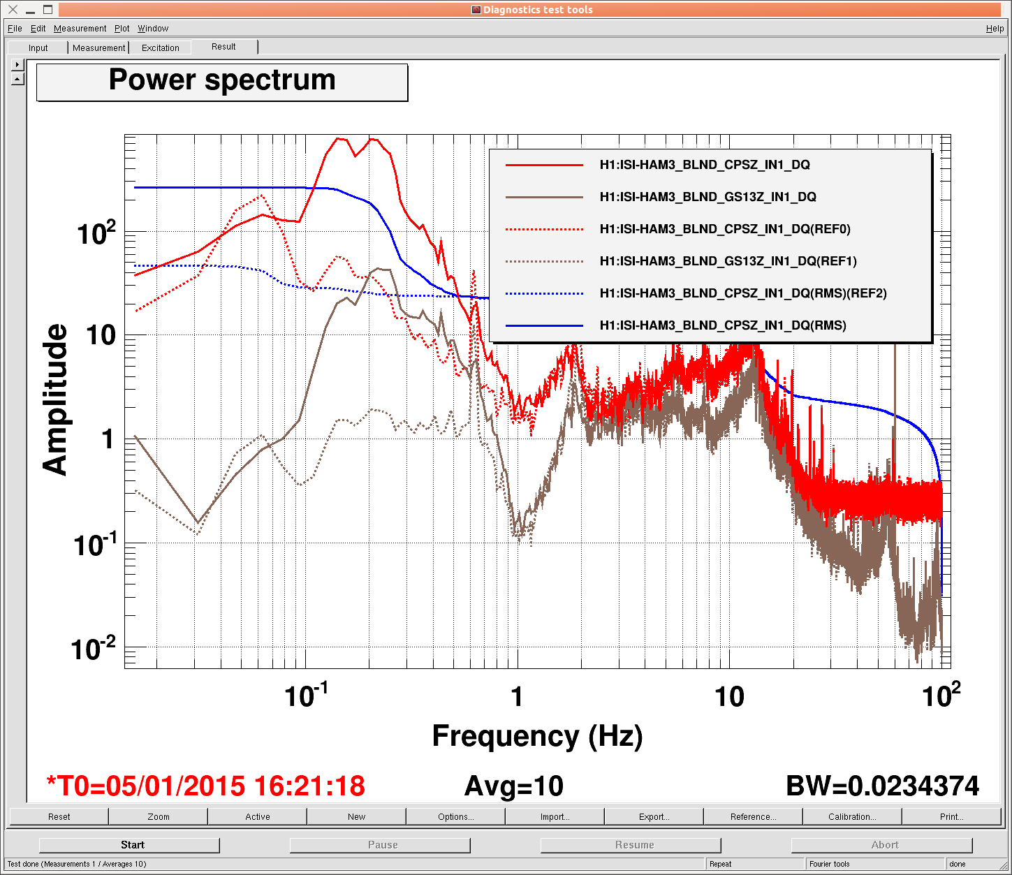
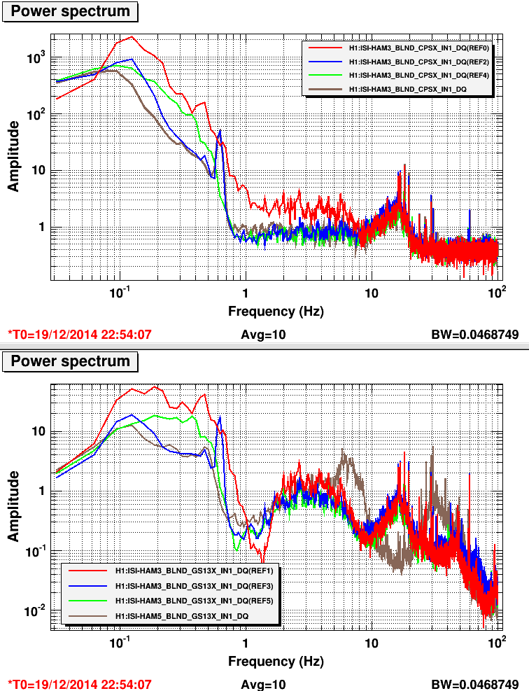
Last year, we thought we had found a configuration using sensor correction on HEPI that worked on HAM3. I was looking (Krishna was, too, he saw it first) at the summary pages over break and noticed that HAM3 still looked like it had the .6hz peak. I came in this morning, checked the configuration and did an on/off measurement, and HAM3 still has the same issue, even when we correct to HEPI instead of the ISI, contrary to what we found last time. See attached plot. Solids are measurement taken with sensor correction off, dashed are with HEPI sensor correction.
Which ground siesmometer was used for the sensor correction?
The HV voltage for the ESD in EX was turned on this afternoon ~3:00PM. Richard spoke to Kyle regarding the vacuum pressure before enabling the HV.

Filiberto C, Richard M.
Kyle, Gerardo

Y-end turbo+QDP80 pumps valved-out but left running for now
The temperature sensor box for the reference cavity temperature stabilisation was swapped out.

old: S1400577
new: S1107831

The old one had a suspected blown regulator.
J. Kissel, R. McCarthy
At my request, after seeing that the EY BSC 10 vacuum pressure has dropped below 1e-5 [Torr] (see attached trend), Richard has turned on the H1 SUS ETMY ESD at ~2pm PST. I'm continuing to commission the chain, and will post functionality results shortly.
Also --
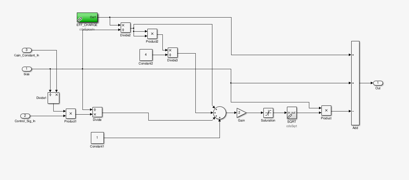
I've found the ESD linearization force coefficient (H1:SUS-ETMX_L3_ESDOUTF_LIN_FORCE_COEFF) to be -180000 [ct]. I don't understand from where this number came, and I couldn't find any aLOGs explaining it. I've logged into to LLO, their coefficient is -512000 [ct]. There's no aLOG describing their number either, but I know from conversations with Joe Betz in early December 2014 that he installed this number when the LLO linearization was switched from before the EUL2ESD matrix to after. When before the EUL2ESD matrix the coefficient was -128000 = - 512000/4 so we was accounting for the factor of 0.25 in EUL2ESD matrix. I suspect that -128000 [ct] came from the following simple model of longitudinal force, F_{tot} on the optic as a result of the quadrant's signal voltage, V_{S} and the bias voltage V_{B}, (which we know is incomplete now -- see LLO aLOG 14853):
F_{tot} = a ( V_{s} - V_{B} )^2
F_{tot} = a ( V_{s}^2 - 2 V_{s} V_{B} + V_{B}^2)
F_{lin} = 2 a V_{s} V_{B}
where F_{lin} is the linear term in the force model, and a< is the force coefficient that turns whatever units V_{S} and V_{B} are in ([ct^2] or [V_{DAC}^2] or [V_{ESD}^2]) into longitudinal force on the test mass in [N]. I *think* the quantity (2 a V_{B}) was mistakenly treated as simply (V_{B}) which has always been held at 128000 [ct] (or the equivalent of 390 [V] on the ESD bias pattern) and the scale factor (2 a) was ignored. Or something. But I don't know.
So I try to make sense of these numbers below.
Looking at what was intended (see T1400321) and what was eventually analytically shown (see T1400490), we want the quantity
F_{ctrl}
-------
2 k V_{B}^2
to be dimensionless, where F_{ctrl} is the force on the optic caused by the ESD. Note that comparing John / Matt / Den's notation against Brett / Joe / my notation, k = a. As written in T1400321, F_{ctrl} was assumed to have units of [N], and V_{B} to have units of [V_{esd}], such that k has units of [ N / (V_{esd}^2) ], and it's the number we all know from John's thesis, k = a = 4.2e-10 [N/V^2]. We now know the number is smaller than that because of the effects of (we think) charge (see, e.g. LHO aLOG 12220, and again LLO aLOG 14853).
In the way that the "force coefficient" has been implemented in the front end code -- as an epics variable that comes into the linearization blockas "Gain_Constant_In," (see attached) -- I think the number magically works out to be ... close. As implemented, the linearized quadrant's signal voltage is as shown in Eq. 13 of T1400490, except that the EPICs record, we'll call it G, is actually multiplied in
V_{S} = V_{C} + V_{B}(1 - sqrt{ 2 [ (F_{ctrl} / V_{B}^2) * G + 1 + (V_{C}/V_{B}) + (V_{C}/V_{B})^{2} * 1/4 ] )}
Note, that we currently have all of the effective charge voltages set to 0 [ct], so the equation just boils down to the expected
V_{S} = V_{B}(1 - sqrt{ 2 [ (F_{ctrl} / V_{B}^2) * G + 1] )}
which means that
G == 1 / (2 k) or k = 1 / (2 G)
and has fundamental dimensions of [V_{esd}^2 / N]. So let's take this "force coefficient," G = -512000 [ct], and turn into fundamental units:
G = 512000 [ct] {{LLO}}
* (20 / 2^18) [V_{dac} / ct]
* 40 [V_{esd} / V_{dac}]
* 1 / (V_{B} * a) [(1 / V_{esd}) . (V_{esd}^{2} / N)]
G = 9.5391e9 [V_{ESD}^2 / N]
==>
k = 5.37e-11 [N/V_{ESD}^2] {{LLO}}
where I've used V_{B} = 400 [V_{esd}] and the canonical a = 4.2e-10 [N/V_{esd}^2] originally from pg 7 of G0900956. That makes LLO's coefficient assume the actuation strength is a factor of 8 lower from the canonical number. For the LHO number,
G = 180000 [ct] {{LHO}}
* (20 / 2^18) [V_{dac} / ct]
* 40 [V_{esd} / V_{dac}]
* 1 / (V_{B} * a) [(1 / V_{esd}) . (V_{esd}^{2} / N)]
G = 3.2697e9 [V_{ESD}^2 / N]
==>
k = 1.53e-10 [N/V_{ESD}^2] {{LHO}}
Which is within a factor of 3 lower, and if the ESD's as weak as we've measured it to be it may be dead on. So maybe whomever stuck in 180000 is much smarter than I.
For now I leave in 180000 [ct], which corresponds to a force coefficient of a = 1.53e-10 [N/V_{ESD}^2].
B. Shapiro, J. Kissel

As usual, two heads are better than one when it comes to these nasty dealings with factors of two (go figure). Brett has caught a subtlety in the front-end implementation that further makes it different from the analytical approach used in T1400321 and T1400490. In summary, we now agree that the LLO and LHO EPICs force coefficients that have been installed are closer to the measured values by a factor of 4, i.e.
G = 512000 [ct] ==> k = 2.0966e-10 [N/V^2]  {{LLO}}
and
G = 180000 [ct] ==> k = 6.1168e-10 [N/V^2]  {{LHO}}
which means, though they still differ from the canonical value (from pg 7 of G0900956)
k = 4.2e-10 [N/V^2]  {{Canonical Model}}
and what we've measured (including charge) (see LHO aLOG 12220, and LLO aLOGs 14853 and 15657)
k = 2e-10 +/- 1.5e-10** [N/V^2] {{Measured}}
they're much closer.

**I've quickly guesstimated the uncertainty based on the above mentioned measurement aLOGs. IMHO, we still don't have a systematic estimate of the uncertainty because we've measured it so view times, in so many different ways, infrequently, and with the ion pumps still valved in, and each test mass has a different charge mean, charge location, and charge variance.

Here's how the aLOG 15809 math should be corrected: The F_{ctrl} and k = a in the analytic equations is assumed to be for full longitudinal force. However, as implemented in the front end, the longitudinal force F_{ctrl} has already been passed through the EUL2ESD matrix, which splits transforms into quadrant basis force F_{ii}, dividing F_{ctrl} by 4. The EPICs force coefficient, G, should therefore *also* be divided by 4, to preserve the ratio
       F_{ctrl}            F_{ii}
       -------      =   ------------
      2 k V_{B}^2     2 k_{ii} V_{B}^2
inside the analytical linearization algorithm. In other words, as we've physically implemented the ESD, on a quadrant-by-quadrant basis,
       F_{ctrl} = F_{UL} + F_{LL} + F_{UR} + F_{LR}
where
       F_{ii} = k_{ii} (V_{ii} - V_{B})^2
and
       k_{ii} = k / 4 = a / 4.
As such, the implemented front-end equation
       V_{ii} = V_{B}(1 - sqrt{ 2 [ (F_{ii} / V_{B}^2) * G  + 1] )}
means that
      G == 1 / 2 k_{ii} = 2 / k = 2 / a
and still has the fundamental units of [V_{esd}^2 / N]. So nothing changes about the above conversation from G in [ct] to G in [V_{esd}^2 / N], its simply that the conversion from G to the more well-known analytical quantity k was off by a factor of 4,
     G = 512000 [ct]             {{LLO}}
         * (20 / 2^18)     [V_{dac} / ct]
         * 40              [V_{esd} / V_{dac}]
         * 1 / (V_{B} * a) [(1 / V_{esd}) . (V_{esd}^{2} / N)]
     G = 9.5391e9 [V_{ESD}^2 / N]
   ==>
     k = 2.0966e-10 [N/V_{ESD}^2]  {{LLO}}
where I've used V_{B} = 400 [V_{esd}] and the canonical a = 4.2e-10 [N/V_{esd}^2] originally from pg 7 of G0900956. That makes LLO's coefficient assume the actuation strength is a factor of 2 lower from the canonical number, pretty darn close to the measured value and definitely within the uncertainty. For the LHO number,
     G = 180000 [ct]             {{LHO}}
         * (20 / 2^18)     [V_{dac} / ct]
         * 40              [V_{esd} / V_{dac}]
         * 1 / (V_{B} * a) [(1 / V_{esd}) . (V_{esd}^{2} / N)]
     G = 3.2697e9 [V_{ESD}^2 / N]
   ==>
     k = 6.1168e-10 [N/V_{ESD}^2]  {{LHO}}
both of which are closer to the measured value as described above.
N. Smith, (transcribed by J. Kissel)

Nic called and fessed up to being the one who installed the -180000 [ct] force coefficient at LHO. Note -- this coefficient only is installed in ETMX, the ETMY coefficient is still the original dummy coefficient of 1.0 [ct].

He informs me that this number was determined *empirically* -- he drove a line at some frequency, and made sure that the requested input amplitude (driven before the linearization algorithm) was the same as the requested output amplitude (the MASTER_OUT channels) at the that frequency, with the linearization both ON and BYPASSED. He recalls measuring this with a DTT session, not just looking at the MEDM screen (good!).

Why does this work out to be roughly the right number? Take a look at the front-end equation again:
      V_{ii} = V_{B}(1 - sqrt{ 2 [ (F_{ii} / V_{B}^2) * G  + 1] ) } )
and let's assume Nic was driving V_{ii} at a strength equal and opposite sign to the bias voltage V_{B}. With the linearization OFF / BYPASSED,
      V_{ii} = - V_{B}
Duh. With the linearization in place,
      V_{ii} = - V_{B} = - V_{B} (1 - sqrt{ 2 [ (F_{ii} / V_{B}^2) * G  + 1] ) } )
so we want the quantity
      (1 - sqrt{ 2 [ (F_{ii} / V_{B}^2) * G  + 1] )} = 1
which only happens if
      (F_{ii} / V_{B}^2) * G = 1.
If Nic wants to create a force close to the maximum, it needs to be close to the maximum of
      F_{ii,max} = 2 k_{ii} V_{B}^2,
which makes
      2 k_{ii} * G = 1
or
      G = 1 / (2 k_{ii}) = 2 / k
which is the same result as in LHO aLOG 15873. Granted, it's late and I've waved my hands a bit, but this is me trying to justify why it feels like it makes sense, at least within the "factor of two-ish" discrepancy between the canonical value and the accepted measurements of the right number.
I've summarized this exploration of Linearization Science in G1500036.
Jim, Hugh, Krishna, Jeff, Fabrice:
We keep investigating the sensor corrction issue on HAM3. What we found yesterday is that it depends on which blends are engaged. We can't explain why yet. We did additional tests today:
- we turned off all CPSs of all HAM-ISI and BSC-ISI in the corner station. No change.
- we checked the jumpers of all HAM3 CPS boards. All good.
- we tried to apply large offset in case it would reduce some kind of cable touching/rubbing (+/-400 um in HEPI Z, and +/-400 um in ISI X,Y, Z). No change.
Finally, we tried to do the Z sensor correction to HEPI. In the plot attached:
- Red curves is HAM3 ISI isolated, no sensor correction
- Green Curve, we turn ON the sensor correction in X and Y to the HAM-ISI
- Blue Curve, we also turn on Z sensor correction to ISI. The 0.6 HZ peak shows up. For some reason it also reduces X at the microseism.
- Brown, we do the Z sensor correction to HEPI instada of ISI. The peak is still there in the CPS, but not in the GS13. It's unclear why.
The last configuration looks good from the GS13s, but it's unclear yet how good it is for the cavity. More info on that is coming.
One more thing that Fabrice forgot to mention in this recap:
   - they restarted the front-end processes for H1ISI and HPI HAM3 (see 15755) -- and also saw no change.

Perhaps during a future maintenance day, we can hard-reboot the entire chassis.

Some further speculation / questions:
- That we *don't* see the feature in the GS13s when we're in low-frequency blend when we feed Z sensor correction to HPI (but we still see the feature in the CPS) rules out the GS13s as the source of the problem.
- The 0.6 [Hz] feature is modifiable by changing the RX / RY blend filters -- higher blend frequency means less 0.6 [Hz] feature. RX/RY implies it's a differential vertical noise, in that one of two of the three CPS are causing the problem.
- Higher blend means more CPS is being used. Wouldn't you think that if the problem is in the CPS, then using more of them would make the problem worse?
- Could it be some subtle, small electronics cross-talk between the STS and the CPS that goes into oscillation?
- We're grasping at straws. This stinks.

@DetChar -- I know it's impossible to figure out the state of the ISIs offline, but can you track this chamber over time and see at least how long we've seen a 0.6 [Hz] feature?
It might take Keith Riles type *days* worth of averaging to find it...
It would be also good take Keith Riles type high-resolution ASDs to find out how sharp the feature is, and to quantify how the heck 1.12 [Hz] is related to 0.6 [Hz]...
In case detchar people are curious about the configuration of this chamber over break, when I came in this morning I found the ISI in what we thought was the good state in December. That is, X&Y sensor correction on the ISI, Z on HEPI and normal blends, isolation loops. I doubt anyone changed the configuration since the 19th of December.


