kiwamu.izumi@LIGO.ORG - posted 00:51, Saturday 20 December 2014 - last comment - 19:45, Saturday 20 December 2014(15763)
more DRMI alignment
Stefan, Kiwamu,
We did some more ASC optimizations tonight in DRMI. We are leaving the DRMI locked overnight to see what drfits on a time scale of hours.
Here is a list of what we did:
-
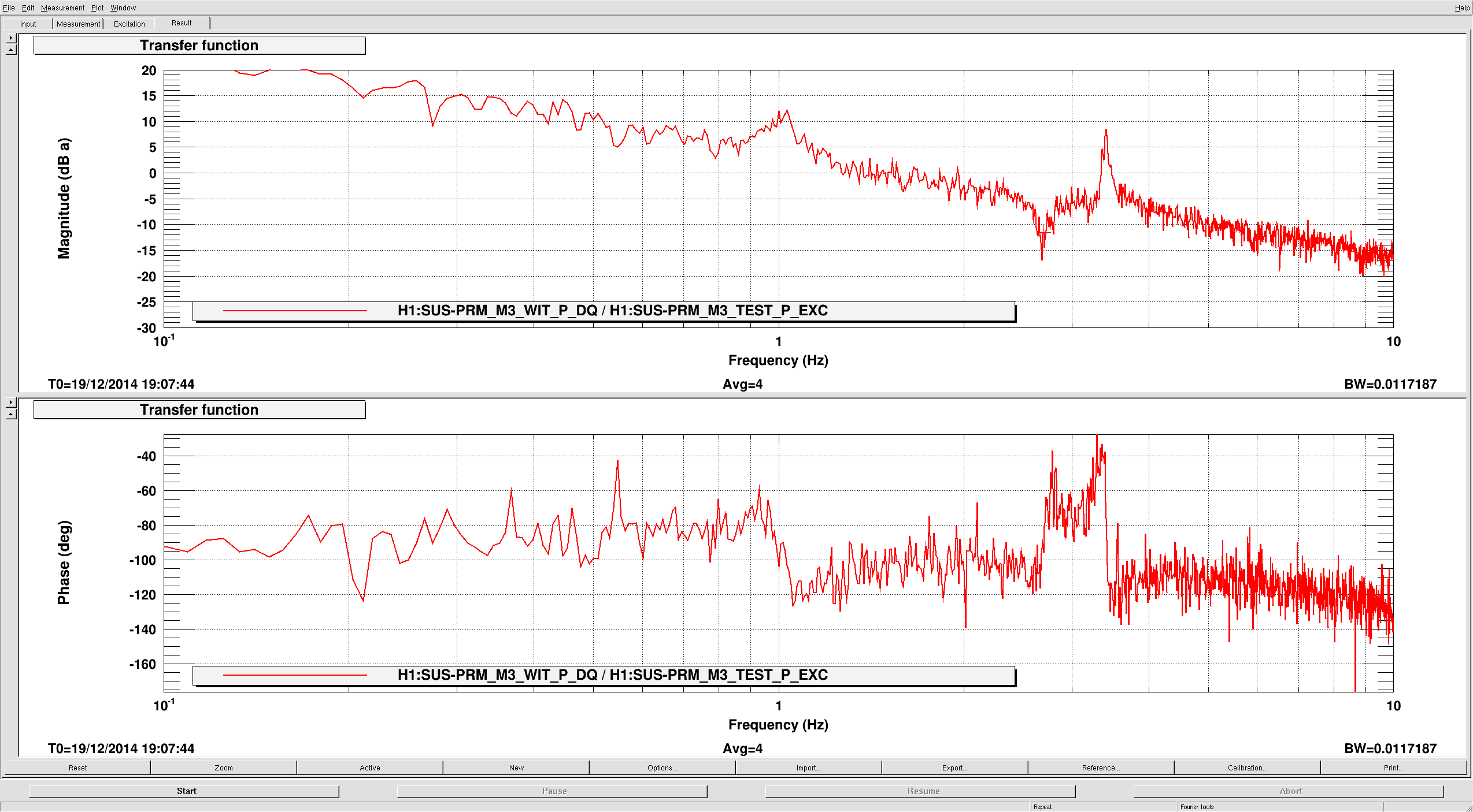
High bandwidth PR3 and PRM ASC loops were engaged. Both use the M3 bottom stage with an almost 1/f open-loop shape.
- PR3 loops = 6 Hz UGF,
- PRM loops = 1 Hz UGF (going above this UGF causes instability at 10 Hz for some unknown reason )
- Off-loading to top stage on PRM, PR3 and BS are newly implemented. The top stages have an integrator so that they keep the DC value when the DRMI drops lock.
-
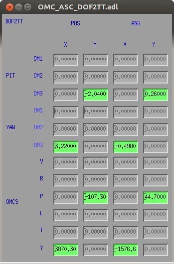
IM4 pointing slow loop is newly engaged. It uses ASC-POP_B. The output matrix is diagonalized with an off-diagonal element for PRM.
- for pitch output matrix, IM4 = 1 and PRM=22.
- for yaw output matrix, IM4 = 1 and PRM = 129.
- The servo points to a non-zero point on POP_B as we were not sure whether it was a good idea to servo it to zero without confirming the arm pointing. In addition, we saw the build-up dropping when we went further away from the nominal offset point, which is another reason why we did not servo it to zero. For now, we put an offset in ASC-POP_B_PIT(YAW)_OFFSET such that we don't loose the current IM4 pointing.
- We moved SR3 (which is one of the uncontrolled mirrors) to see what signal responds to it. It seems that REFL_B_45I is sensitive to this mirror, but currently SRM is suppressing this sensor with a slow bandwidth. Stefan will look into this mirror during the weekend.
All the modifications and new loops are coded in not only in the ISC_DRMI guardian but also ISC_DOF guardian so that they do not mess up the initial alignment WFSing.

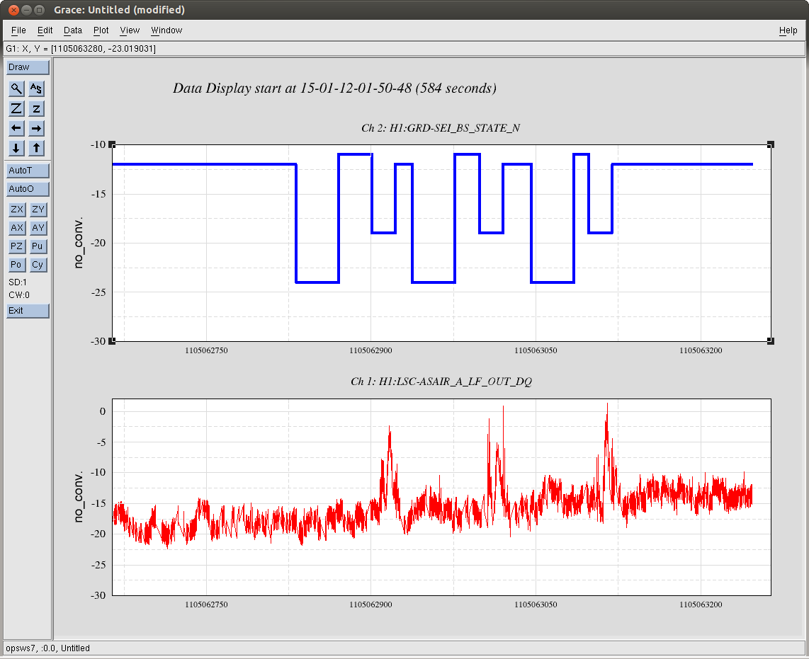
Lock lost at 1103105129 ~ 2014-12-20-10-04 UTC
Attached are some trends leading up to the loss of lock, it lasted for about 2 hours.
It looks like something could have rung up the input to th WFS servo loops and this caused some instability, I've attached some trends that show the in/outs of the ASC WFs at tthe time of unloking but it's hard to tell who's the culprit exactly.