J. Kissel
In summary:
(1) Turn on X, Y, and Z sensor correction for HAMs 2 and 5, using the standard Hua Filter scheme (see T1200285), with tuned gains.
(2) Use LLO's M1 OSEM Damping filters and gains.
(3) Turn off optical lever damping so we don't have worry about maintaining optical levers to as great care.
-------
This continues (and hopefully resolves) the study of why PR3 and SR3 (both HLTSs) are angularly noisy, began by Kiwamu (see LHO aLOG 15048), and continued in a prior aLOG by me (see LHO aLOG 15154). I had started today thinking that I would do the usual full modeling suite, and this time include the optical lever damping. But after a little bit of exploring, I found that the L1 HLTS, H1 PR3, and H1 SR3 were using in various, completely different damping schemes, the performance of the optical levers are radically different, so a noise projection would be difficult, and the L1 vs. H1 HAM ISIs perform significantly different. So, since a "representative" model seemed impossible, as did the thought of making an individual model for all four suspensions and comparing, I've just spent the time gathering proof of what we need to do to make them much better. Once we get all of the above three steps completed *then* I'll make a full model suite of the performance.
Here's the details explaining how I can to these conclusions. They're supported by the first and only attachment.
(3) Turn off optical lever damping.
Pages 1 and 2 of the attached show the wide variety of performance on the optical levers. Page 3 and 4 show the H1 the levers are in loop, but only with a bandwidth from 0.4 to 1 [Hz] (see design for SR3 in LHO aLOG 14719). There seems to be some effort toward rolling off the noise, but it seems quite unrelated to the actually noise performance of the levers at high frequency.
LLO *had* used optical lever damping sporadically on L1 PR3, but they're currently not using it and haven't since Oct 17 2014. Given that the damping is so much strong and the input motion is so much smaller, this makes sense that its not needed. Further -- even with L1 SR3 aligned, the location to which, presumably, the optical lever has been centered -- the performance of the optical lever spectra is not limited by residual ground motion of the optic. So it's most certainly unusable for control.
Including optical levers in the local damping scheme complicates the remaining dynamics of the suspension (and perhaps more to the point, the subsequent modeling of it), and getting used to relying on them means they'll be left on and most certainly reinject noise above their bandwidth unless the loops are custom tailored to the ever-evolving optical lever noise. So if we can achieve the same level of local damping with the top mass OSEMs, and improve the performance of the ISIs, let's do it.
(1) Turn on X, Y, and Z sensor correction for HAMs 2 and 5, using the standard Hua Filter scheme (see T1200285), with tuned gains.
Pages 5 through 7 compare the performance of the HAM2 and HAM5 ISIs, highlighting the degrees of freedom which contribute to L, P and Y at the optic.
Remember, the L at the suspension point is the dominant contributor to L *and* P at the test mass, at all frequencies (see pgs 5 and 33 of the second attachment to LLO aLOG 7907). In turn, X and RY (for PR3) and Y and RX (for SR3) are the dominant contributors to L at the suspension point. Y at the optic is all Y at the susp. point, which is all RZ of the table.
Though I'm not sure what the H1 HAMs have worse performance than the L1 HAMs between 2 and 8 [Hz] (that should be investigated further), I certainly know that the *drastic* difference between 0.3 [Hz] and 1 [Hz] is because LLO has sensor correction for all DOFs turned on. Poking around at LLO, I've found that the sensor correction is nothing particularly fancy -- it's just the standard Hua filter scheme, with a single, gain only Match filter at the output to tune better match STS gain to the displacement sensors (those gains are a correction of ~10-20%, matched to a ridiculously high precision [where its unclear if the precision is needed]). HAM2 uses the HAM2 STS (STS A), and HAM5 uses the HAM5 STS (STS C), as expected.
At the first L and P resonances of the HLTS, there's a possibility for the following improvement if we get to LLO's level of isolation:
Frequency [Hz] Table DOF Performance Ratio
0.64 HAM2 X 6.23 / 0.11 = 56.6
HAM5 Y 5.29 / 0.08 = 66.1
0.74 HAM2 X 1.87 / 0.03 = 62.3
HAM5 Y 1.42 / 0.02 = 71.0
and as we know by now, its these lowest resonance frequencies that dominate the RMS motion of the optic.
All this being said, except for between 0.2 [Hz] and 0.6 [Hz], LLO is kicking the snot out of the "requirements." Nice job! I'm very confident that we can do just as well here at LHO. The trick will be to get the HAM2 and HAM3 sensor correction up at the same time, so that we don't introduce and relative low frequency noise in the recycling cavities.
P.S. There're some pretty nasty sharp features and associated harmonics in the L1 HAM5 ISI's RX and RZ spectrum ... we should get that fixed -- they're obviously electronic, particularly ugly, and might affect pulsar searches.
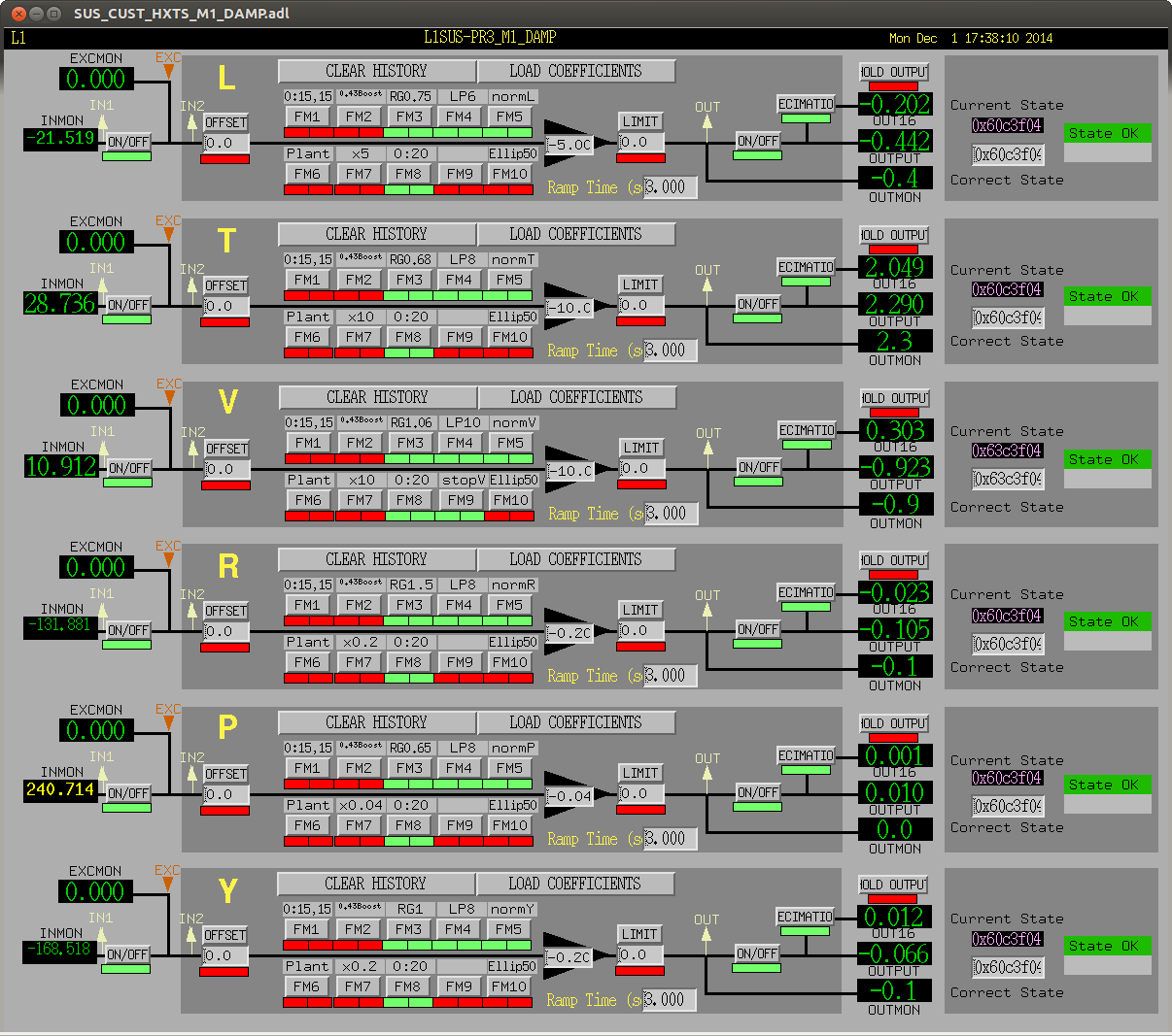
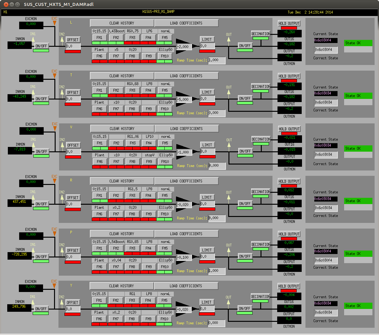
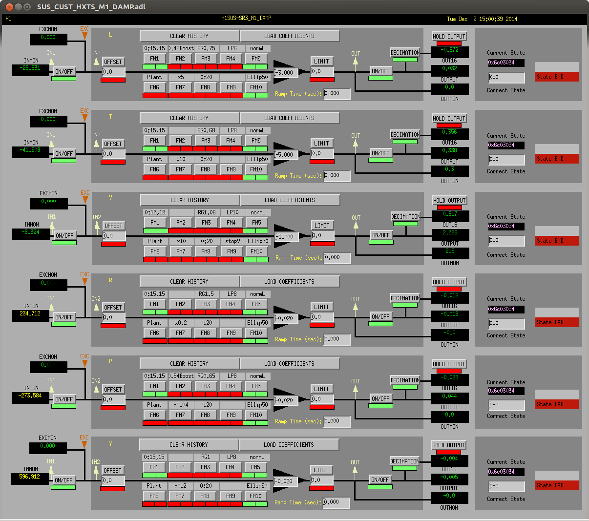
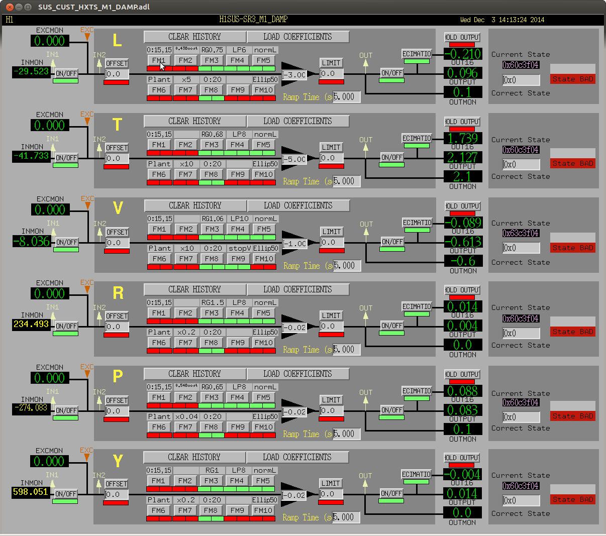
(2) Use LLO's M1 OSEM Damping filters and gains.
Pages 8 and 9 highlight the DRASTIC difference in damping loop filters. I hesitate to call the H1 HLTS filters a "design," because I know they were copied from the QUADs (hence the 0.43 [Hz] and 0.56 [Hz] resonant gains in the L and P filters, respectively). There's no reason at all we shouldn't just switch to the LLO design immediately -- these aren't under global control so we need not worry about changing any global control transfer functions, and though I haven't modeled it (yet) the increase in gain at just about all frequencies, especially what's focused at the *actual* first L and P modes of the HLTS. With the switch, we would get a factor of 16.2 increase in gain at 0.75 [Hz] in the L loop (which presumable will hit the same mode in P as well), and a factor of 44 increase in gain at the first, 1 [Hz], Y resonance.
With steps (1) and (2) complete, that means we can expect to improve the Y and P motion at the optic, at the main resonances by as much as three orders of magnitude.