andres.ramirez@LIGO.ORG - posted 08:57, Friday 24 October 2014 (14605)
ISS Diffracted Power
The ISS Diffracted Power was out of range this morning. It is been set to the proper values.
The ISS Diffracted Power was out of range this morning. It is been set to the proper values.
We have limited access to the LVEA today. Therefore, try to avoid going in by any reason.
model restarts logged for Thu 23/Oct/2014
2014_10_23 02:40 h1fw0
2014_10_23 09:28 h1fw1
2014_10_23 15:53 h1nds0
2014_10_23 16:23 h1nds0
2014_10_23 16:26 h1nds0
unexpected restart of fw's. Manual restarts of nds0 after various issues (due to large data requests)
Kiwamu, Rana
As we discussed in today's meeting, we need to improve the DRMI acquisition so that its better than 1 lock per 30 minutes (the situation all week). Kiwamu spent much of today examining a bunch of lock acquisition attempts and trying to decipher what was happening by plotting the time series and making up good stories. He will put in some details in the morning.
Around midnight, after we gave up on BS OL tuning, we decided to adjust the DRMI loop gains and the loop turn on thresholds. We had been using high thresholds to turn on PRC, then MICH, then SRC. We noticed that LLO has been leaving PRC ON all the time and then triggering SRC first and then MICH second. So we put in something similar and adjusted the thresholds to approximate the levels they were using roughly. We then also lowered the MICH and SRCL UGFs by a factor of a few to also move more towards the LLO setup.
These few steps seem to have made a large improvement. Just after we made the changes, we got several locks within 10 minutes (from midnight until 00:10). At first there was some small oscillations at a few Hz, but we think this came from having a 5 Hz MICH UGF and a triggered 3 Hz boost. We adjusted the triggering to use zero history and no ramp for the integrators and the oscillations disappeared. After that, we just had some short locks with bad alignment.
Its only a single stretch of 10 minutes, but the improvement was so dramatic that I am willing to say we are now in a region of parameter space which allows fine tuning of loops shapes and thresholds. We'll need to try with a fresh alignment to be sure, but indications are positive. We are also going to import Jenne's 'AND' logic from the 40m LSC system to see if we can make a better SRC trigger.
Alexa, Evan
Daniel and Rana have pointed out that it doesn't make much sense to use AS_A_RF45 as a sensor for controlling the angular DOFs of sideband-locked PRMI/DRMI: the carrier is (intentionally) not resonant in these configurations, meaning that the 45 MHz RF signal is dominated by the 45 MHz sidebands beating against a weak (and potentially spatially junky) carrier signal. What we want instead is a signal which involves some sort of beating with the 9 MHz TEM00 mode, since this is resonant inside sideband-locked PRMI/DRMI. We propose to use AS_A_RF36 to feed back onto BS M2, since the 36 MHz signal involves the beating of the 9 MHz sidebands with the (co-resonant) 45 MHz sidebands. This is what is used at LLO (see Den's slides at G1400981).
We've done the following to prepare AS_A_RF36Q for use with the ASC loops:
To proceed from here, we need to:
J. Kissel, R. Adhikari, A. Staley, D. Sigg, D. Barker, J. Batch, H. Radkins

Something non-nonsensical happened to H1 SUS MC2 this afternoon, it's fixed now. Too many things had gone on, lots of red herrings causing more random button clicking, and not enough people were fully aware of tall components involved to make sense of it while it was going on. I've tried my best to find out what happened by trending channel after channel -- I quote the time-line of everything I could find, but there's no smoking gun. Chalk this up to a one-off badness. IMHO, there's no point in chasing further because too many thing things happened at once, too quickly, without a clear diagnosis or clear plan to fix it.

As an aside, we need to standardize our HSTS damping loops. Its my fault for not having a complete model and organized damping loop design for these suspensions. In its absence, folks have found various configurations that make them happy that day, and now, because it "works", no one wants to change anything nor knows what the "right" status is.


All times UTC on 2014-Oct-23 (but 14:08 UTC is 7:08a PDT 2014-Oct-23)
14:08 IMC Flailing for lock, rapidly bouncing between Guardian state INIT and LOCKED.
  |
  |   16:20 h1fw1 dies, dropping all trend data for a few minutes. This is the default nds server for data viewer, so it looks like this is the cause of the problem, [first red herring] but looking at h1fw0 data shows not drop out.
  V   16:23 H1 SUS MC2 starts to veer off in Yaw by hundreds of micro-radians
16:24
16:26 H1 SUS MC2 LF and RT output signals (the top-stage, M1 OSEMs which control longitudinal and yaw) gradually start to increase their signal
16:35 Hugh begins to take down *HAM2* (Note -- NOT HAM3, the chamber in which H1 SUS MC2 lives [second red herring]). Hugh later confirms that HAM3 ISI and HPI remain rock solid throughout.
  |
  |  Problems with correcting ISI matrix elements means HAM2 ISI fights to come up and down (see LHO aLOG 14594)
  |  16:40 UTC H1SUSMC2 top mass M1 outputs begin to constantly saturate
  V
19:07 HAM2 ISI recovers from problems
20:18 IMC guardian atempts to resume locking
21:03 Alexa find that H1 SUS MC2 is off in the weeds in Yaw by looking only at the bottom stage OSEMs, moves the alignment sliders hundreds of urads to push the top stage M1 to compensate for what she sees
21:07 IMC WFS automatically begin trying to compensate for Alexa by requesting hundered the M1 LOCK Y output hundreds of urads in the opposite direction
21:08 IMC WFS have compensated for Alexa, and restored MC2 to early morning location
21:31 Alexa turns OFF the IMC by seting the LSC-MC_GAIN to zero, instead of asking the guardian to stop trying to lock. IMC LSC control is NO LONGER GOING TO THE SUSPENSION [third red herring]
21:34:27 Rana turns on FM10 (Ellip50) of the DAMP L bank, changing the SWSTAT from 5140 (only FM3 and FM5) to 5652. The damping loops have been at SWSTAT 5140 for 120 days (separate trend), implying the "correct" state*** for MC2 is with FM2 OFF.
21:34:37 H1 SUS MC2 User Watchdog Trips, killing all output to M1 TOP stage
21:34:40 H1 SUS MC2 IOP Watchdog Trips, killing all output to entire suspension
21:35 H1 SUS MC2 longitudinal damping loops begin oscillating, because damping has been turned off and suspension is shaking -- BUT NO OUTPUT IS GOING OUT, so there's nothing wrong with the damping loops [fourth red herring].
21:35:56 USER watchdog is untripped, IOP Watchdog is locked up (won't reset), unclear why.
21:39 Rana tries different configurations of the L filter banks, trying to find one that's stable, settles back on FM3, FM5, and FM10.
21:39:42 Alexa successfully untrips IOP watchdog. Unclear why.
21:46 Alexa turns the MC_GAIN back to 1.0, allowing IMC control to resume requesting the IMC to be locked, though some how the guardian status claims the IMC has been in the locked state since 21:07, with only short dropouts at 21:13, and 21:30. I don't know what the IMC guardian watches, but it doesn't seem to be accurate.
21:47 IMC locks stably. Problems resolved.


Also, the h1nds0 died thrice after I'd switch to using it to avoid the h1fw1 data drop out (only reported once in LHO aLOG 14598).

DetChar is welcome to take a stab at it, but there's just about zero chance of reconstructing this perfect storm tornado.

*** This was NOT the problem, but I summarize the complete dis-array of the HSTS L damping loops:
MC1  FM3, FM5,       G = -3
MC2  FM3, FM5, FM10, G = -3
MC3  FM3, FM5,       G = -3
PRM  FM3, FM5,       G = -1.55
PR2  FM3, FM5, FM10, G = -1.55
SR2  FM3, FM5        G = -1.55
SRM  FM3, FM5        G = -0.55

I would post dataviewer trends, but the time axes tick labels are spaced so far apart for an 8 hour trend that it's useless. I can zoom in live, and use my cursor to identify exact times (which is how I composed the above timeline), but upon zooming in, the time axis tick labels go from far to sparse to unreadably over-dense.

#houseofcards
The h1nds0 computer died with a kernel panic, fatal exception to interrupt. Rebooted.
J. Warner, K. Venkateswara
This morning we tried X and Z sensor to HEPI. The results on Z are very positive. The first plot of the first pdf shows the ground Z motion / Stage 1 T240Z motion without and with Z sensor correction. It shows an improvement of ~10 at the microseism, with a factor ~2 reinjection between 20-50 mHz. The next plot of the first pdf shows the Pitch motion without and with Z sensor correction, which again shows an improvement of ~10 at the microseism.
With X, things are a bit different. The first plot of the second pdf shows the ground X motion / Stage 1 T240X motion without and with X sensor correction. It shows an improvement of ~2-5 between a large range 20 mHz to 2 Hz, with maybe a factor ~2 reinjection at 10 mHz. This was similar to the increase in performance when we tried sensor correction to Stage 1. The next plot of the second pdf shows the Pitch and Yaw motion without and with X sensor correction, which looks the same above 50 mhz, but shows a factor ~5 increase below that frequency. We saw a similar increase when doing the sensor correction to X as described in 14570. Jim and I suspect that the tilt and yaw decoupling from X at Stage 1 (or HEPI) might not be good enough so we will repeat that measurement later.
Bottomline: Z sensor correction to HEPI works great. It works better than Z sensor correction to Stage 1. X sensor correction to HEPI/Stage 1 produces similar results - It improves performance at Stage 1 X but increases Pitch and Yaw motion at low frequencies, probably due to tilt and yaw coupling with X drive/sensing. Better tilt decoupling may help.
Edit: I had a calibration error in the plots, which has now been corrected.
LVEA: Laser Hazard
Observation Bit: Commissioning

08:46 Betsy – Quad work in LVEA West Bay
11:46 Rick & Joe – End-Y PCal transmitter installation
11:53 Betsy – Out of LVEA
12:50 Jonathan – Restart of Mobil Authentication System
12:56 Krishna – Going to End-X to work on BRS
13:57 Betsy & Travis – Quad work in LVEA West Bay
14:06 Filiberto – End-Y install PCal power supplies in rack
15:41 Betsy & Travis out of LVEA
Hugo & Hugh
With new ISI TFs from Sept 16 when the ISI was Under Vacuum with the HEPI Position Loops closed, I made new Level 3 control scripts for HAM2. I took the ISI down with Guardian pausing the manager and putting the ISI in READY.
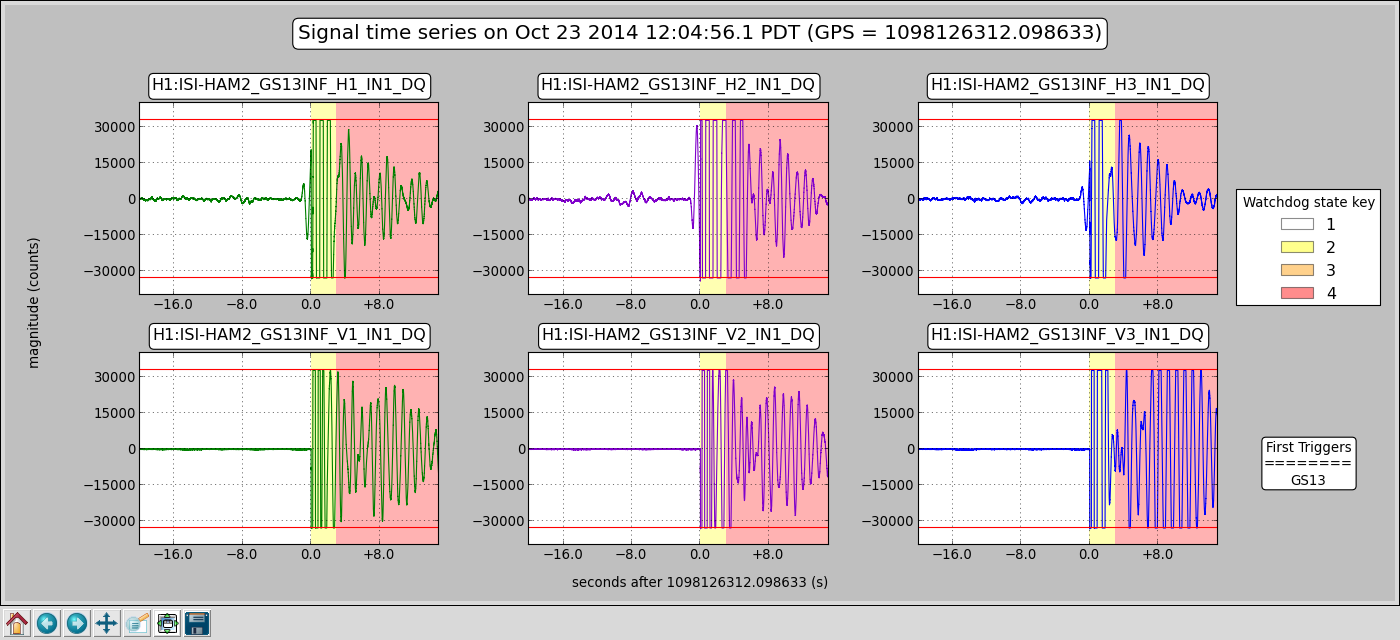
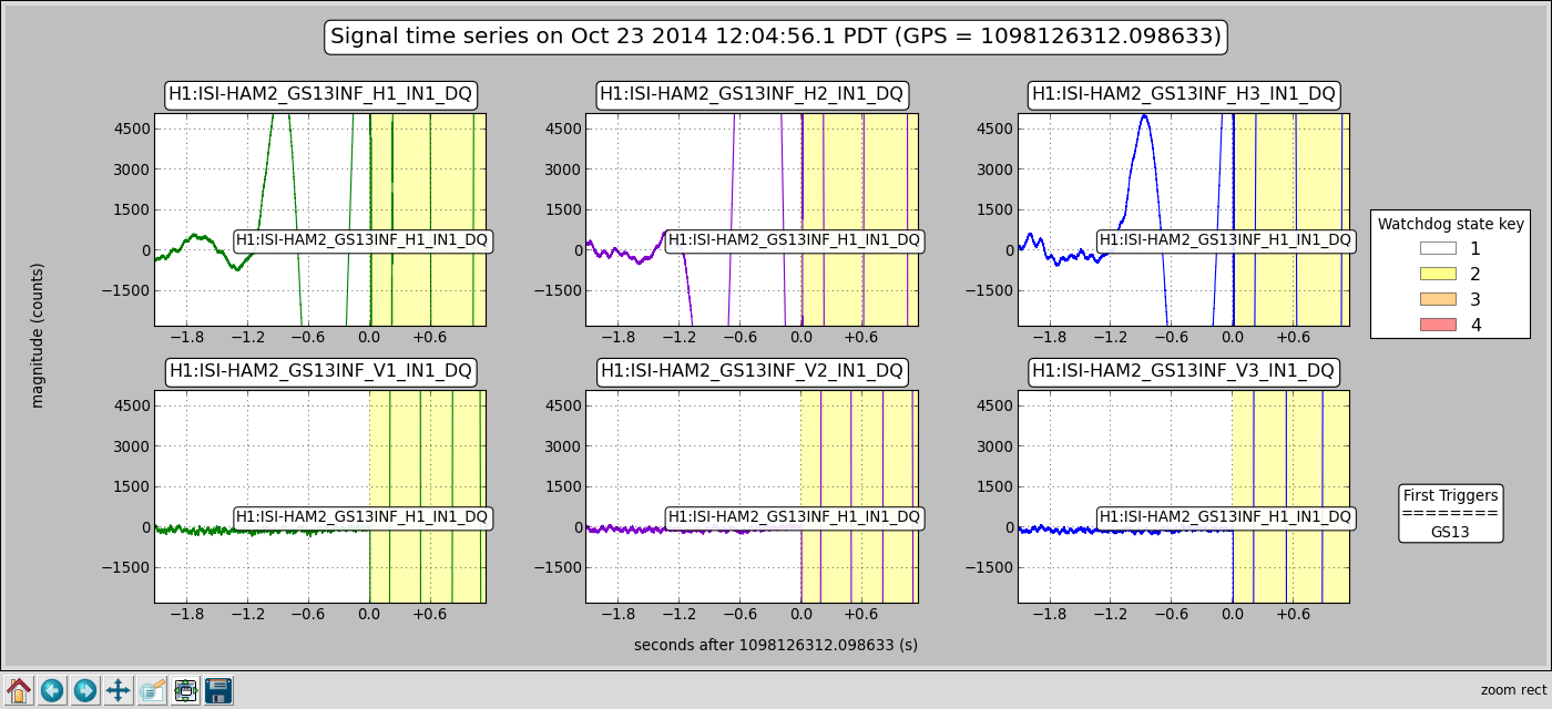
In this state, the local 2 cartesian (& back) matrices were corrected--the X Y RX & RY signs were incorrect-- using the Populate_Matrices_HAM_ISI.m function. As expected, the cartesian sign of these dofs switched and the Target Position was correspondingly changed (by hand.) I then loaded the new filter file. Everything as expected so far. When the ISI Guardian was set back to High Isolate, it performed as expected until it was changing the horizontal dof gains from 0.01 to 1.0. At this point it trips in a fraction of a second on the GS13. In subsequent attempts it almost always repeats this behaviour although sometimes the trip was the actuator rather than the GS13, see the attached for example and zoom in.
OK so I screwed up the controllers. We tried level 2 controllers. Wait Guardian isn't set up to do level 2 so I try the old ISI Command scripts: yes it works on level 2 & level 1...
So Okay, I must have screwed up the controllers. I reverted back to the achive file that was made Oct2 10:16: still Guardian trips the level3 attempt at the same spot... revert back to Oct2 10:13 (what's up with that?.) Same result.
We try some manual turn on, that is 1 dof at a time, hey we can isolated this way. Then we take it down again and try with Guardian, no, it still turns on the Vertical Dofs fine but trips when switching the Horizontal dofs from0.01 to 1.0 gain.
Then! Then we try level 3 with the old ISI command scripts--it works! We turn Guardian back on, take the ISI down to ready and then attempt to get back to Isolation, nope, sorry, still trips. Back up to level 3 Isolation with the old ISI command scripts. This is where it sits...Strange.
Strange in that the ISI command script turns RX & RY dofs on first while Guardian does Z RX & RY first. Then when the command scripts have to do Z X Y & RZ, Guardian only has to do X Y & RZ. Plus, guardian does everything sequentially as in it waits for boosts to be on before he next step whereas the old command scripts are often doing more things at once such as engaging the boost while starting the Alignment bias servoing.
So we have to conclude that something must be up with Guardian although it seems unlikely. I restarted all Guardians 16 October and all went back to high isolate with no problem.
We have a before these changes performance plot. We'll take another look after things settle down and compare.
Summary
Matrices and Controllers reverted but ISI will not Isolate with Guardian. It does Isolate using the old ISI Command Scripts.
re "I restarted all Guardians 16 October and all went back to high isolate with no problem."
I actually didn't bring the isolation down. The Guardian was restarted without impacting the platform, so it could be that there is a long standing issue with Guardian. Based on the Watchdog trip indicator, Oct 2 was the last time the HAM2 ISI tripped but of course that doesn't mean someone might have run the ISI down with the Guardian. There are some ODC BIt changes around 16 Oct...
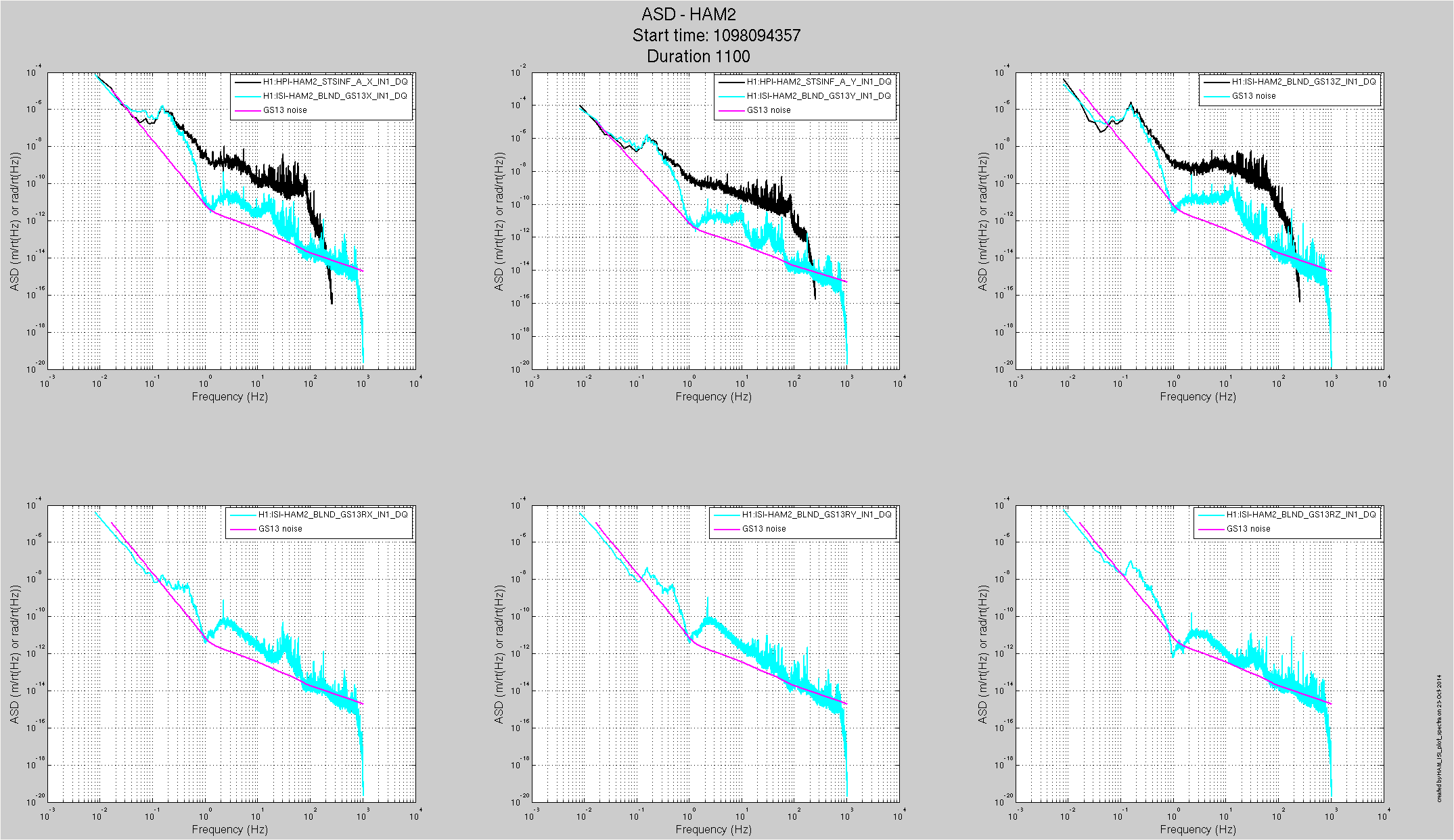
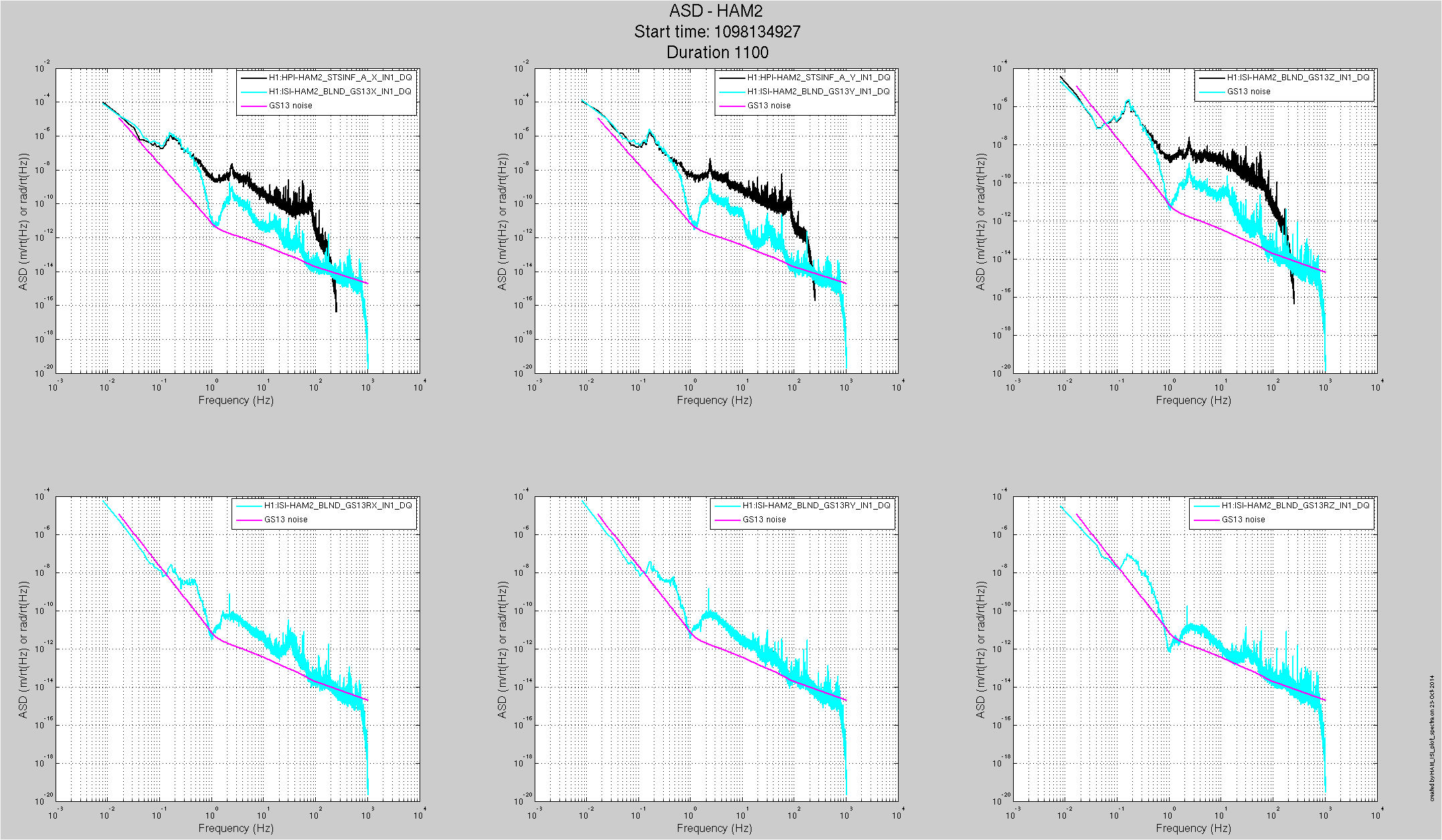
It may not be a fair comparison: The first attached plot is the ground motion and HAM2 GS13 spectra at 3 this morning with 100mhz blends on the X Y Z dofs, 01_28 blends elsewhere. The second plot is from 1430pdt where we have 01_28 filters on all dofs. Of course the input ground motion is different,there is more motion on the ISI X Y Z dofs in the 1 to 10hz band. The other dofs are pretty similar. We'll put these blends back and check when the commissioners can deal with the change.
Looked at EY seismometer yesterday morning and found unit disconnected from power supply. Re-terminated cable ends with appropriate banana connectors. Robert S. reports spectrum for unit looks good.
model restarts logged for Wed 22/Oct/2014
2014_10_22 08:29 h1fw1
2014_10_22 09:25 h1fw1
2014_10_22 19:28 h1fw1
all restarts unexpected
Rana, Evan, Kiwamu, Alexa
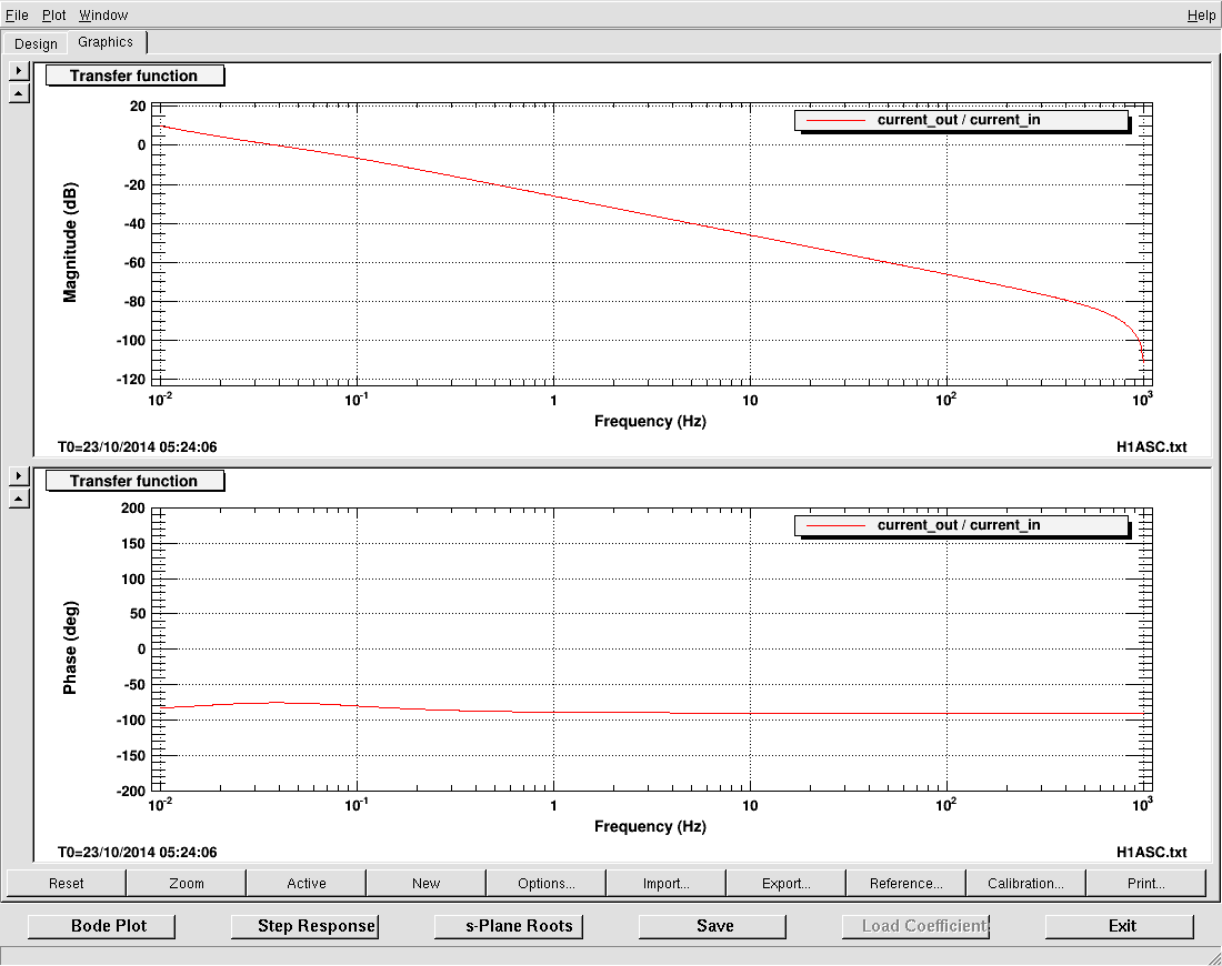
Tonight we worked on the ASC WFS again. We noticed that the P,Y had different integrators loaded even though they were named the same thing. There was also a high frequency gain of -30dB in the integretor. We have adjusted this filter (see attached photo of the new filter FM1, and second image with FM1 and FM2 on). We also aborbed some of the overall filter gain in FM1, so that the gains are not as small as before. We can now close the loops for PRMI, and they are stable. The configuration is as follows:
| PRCL | MICH | |
| Signal | RELF_A_RF9_I | ASC_A_RF45_Q |
| Gain (P.Y) | (-0.01,-0.01) | (-0.0003,0.0003) |
| Optic | PRM | BS |
| Settle time | 1 min | 10 sec |
We noticed that there is a bit of coupling between the REFL_A_RF9_I pitch and yaw signal; however if the DC alignment is suffeciently good the loop is still stable. The ASC WFS then bring POPAIR_B_RF18_I_MON to ~170cts. These changes are reflected in the guardian. (The old gains are commented out, and the old FM1 filters remain in the SRCL loop in case we need to revert anything).
We continued on to DRMI. The PRCL loop worked fine. However, the above configurations for MICH failed. The loops would drive the BS cntrl too far off too quickly, and we would lose lock. Unfortunately, the DRMI lock acquisition time is extremely long, and trying to adjust this loop was difficult. We got tired....
Rana, Kiwamu
In order to study why the DRMI seems to lock faster at 1 Watt (see alog 14508), we checked the RF level of REFLAIR_A which is the one we use for acquiring lock of the DRMI.
The RF level at the output of the PD can be as high as -5 dBm and 3 dBm at maximum for 9 and 45 MHz respectively. This may be a bit too high, but certainly not outrageously too high.
(some details)
We hooked up a 300 MHz oscilloscope to the RF mon of the demod boards and checked the RMS value of the RF signals when the DRMI was flashing. Using the trigger on the scope, we captured two incidents where the RF level was high as follows:
Since the attenuation from the RF input to the RF mon on the demod board is 23 dBm, the real input signals must have been bigger by 23 dB than what we observed on the scope. Therefore the highest signals we expect at the output of the RFPD are -5 dBm and 3 dBm at 9 and 45 MHz respectively.
Note that when the DRMI was locked, there was almost no RF signals. We occasionally saw small signal of about -40 dBm at 45 MHz which we think was some kind of seismic excitation.
Jeff, Rana, Alexa, Kiwamu, Evan
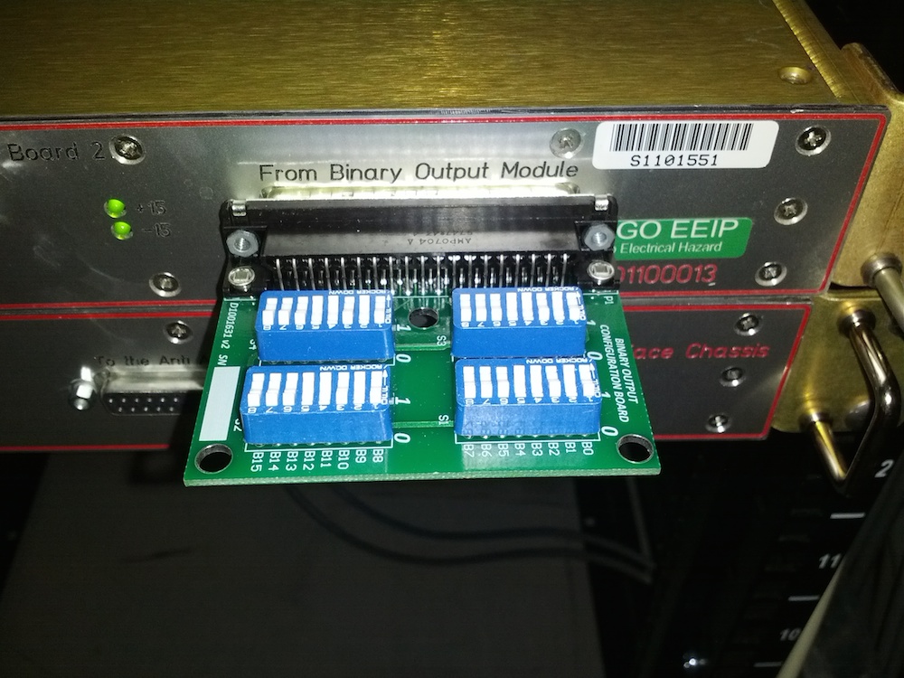
Rana noticed that the BS oplev spectra (pitch and yaw) were suspiciously flat, perhaps indicating that they were dominated by ADC noise.
To fix this, Rana and I attached a DIP-switch jumper board (D1001631v2) to the 37-pin dsub on the BS oplev whitening board. This allows us to set bits that control the gain and whitening.
For each of the four segments, we flipped bits 2 and 4 (which increases the gain) and bit 5 (which engages a single whitening stage) to high; all others are low. Then we engaged the antiwhitening filters for each segment.
The first attachment shows the BS oplev spectra before (green, brown) and after (cyan, magenta) the gain+whitening+antiwhitening, with the loop off. We now appear to be resolving more features in the spectra.
The second attachment shows the BS oplev spectra after gain+whitening+antiwhitening, with the loop off (cyan, magenta) and on (red, blue).
J. Kissel

I've installed the refined alignment slider gains from 14405, and subsequently measured the optical lever calibration gain refinement for H1SUSETMX and H1SUSETMY using the method described in LHO aLOGs 14387 and 14312. I attach fits to the data points. The newly refined oplev calibration gains are
EX P = 81.2  [urad/ct]
   Y = 115.2 [urad/ct]
EY P = 77.94 [urad/ct]
   Y = 53.55 [urad/ct]
Further, I've installed the already-computed, refined optical lever calibration gains for H1SUSBS from LHO aLOG 14387, compensated for the change in the optical lever damping loops, and confirmed the loop is still functional.

I've captured new safe.snaps for all three suspensions to ensure these values stick.

As such, all core-optic, BSC suspensions have optical lever gains refined precisely to a few hundredths of a percent (i.e. the separation of the baffle diodes, ~30 [cm] over the length of the arms 4 [km].)

Details

The ETMX P fitted correction factor is:
0.8805 ["urad"/urad]
The new ETMX oplev P calibration should be:
71.5 ["urad"/ct] * 1.136 [urad/"urad"] = 81.2 [urad/ct]
The ETMX Y fitted correction factor is:
1.058 ["urad"/urad]
The new ETMX oplev Y calibration should be:
121.8 ["urad"/ct] * 0.9455 [urad/"urad"] = 115.2 [urad/ct]
The ETMY P fitted correction factor is:
1.225 ["urad"/urad]
The new ETMY oplev P calibration should be:
95.5 ["urad"/ct] * 0.8161 [urad/"urad"] = 77.94 [urad/ct]
The ETMY Y fitted correction factor is:
1.295 ["urad"/urad]
The new ETMY oplev Y calibration should be:
69.33 ["urad"/ct] * 0.7724 [urad/"urad"] = 53.55 [urad/ct]

The raw measurement data and script to process it can be found here:

/ligo/home/jeffrey.kissel/2014-10-22/
calibratebsoplev_20141021.m
2014-10-22_H1SUSETMX_OplevCalibration_P_Offsets_10sec_avg.txt
2014-10-22_H1SUSETMX_OplevCalibration_Y_Offsets_10sec_avg.txt
2014-10-22_H1SUSETMY_OplevCalibration_P_Offsets_10sec_avg.txt
2014-10-22_H1SUSETMY_OplevCalibration_Y_Offsets_10sec_avg.txt
9:23 am, Filiberto to X-End station to pick up tools then to head to work at the Y-End station, also fix the seismometer.
9:30 am, Aaron to the X-End station to terminate a cable.
10:17 am, Karen to Y-End and Y-Mid stations, cleaning duties.
11:10 am, Betsy to the CS VEA, look for items by the PSL area.
11:30 am, Betsy exits CS VEA.
11:43 am, Kyle to Y-End station VEA area, working with purge air system.
11:48 am, Karen heading back from Y-Mid station.
12:12 pm, Kyle leaving Y-End station.
1:26 pm, Kyle to Y-End station VEA area, continue with work.
2:25 pm, Kyle leaving Y-End station.
3:35 pm, Kyle heading back to Y-End station, continue with work.
3:54 pm, Doug to the CS VEA, looking a small circuit board.
Following the measurement of the power recycling gain (alog 14532), I made an estimation of round trip loss in the power recycling cavity.
In order to explain the recycling gan of 21 for the 45 MHz sidebands, round trip loss needs to be 2.3%.
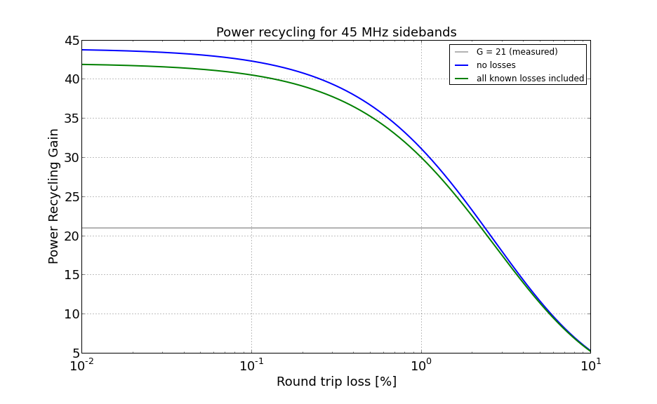
The plot shown above is power recycling gain for the 45 MHz sidebands as a function of round trip loss. The blue curve represents the one without losses but with the effect of the Schnupp asymmetry. The green one is that with all the known losses included.
For more details, see the attached python code. Also, the highest gain we can achieve is 42 for the 45 MHz without round trip losses. Note that I assumed both ITMs to have the same curvature and also I have not included the mode matching effect.

