Summary:
Following the PR2 scan from last week (https://alog.ligo-wa.caltech.edu/aLOG/index.php?callRep=14845), I used a single bounce beam from IX and scanned the BS while using SR2 to center the beam on AS_C. I also scanned SR3 while using the same ASC feedback on SR2.
There's at least 0.7% or so in the SRC-AS path donwstream of SR3. Tomorrow I'll roughly center SR2 by looking at the SR2 baffle and scanning SR3, then scan SR2 to maximize AS_C while keeping AS_C centered using pico.
The beam might become off-centered on SRM depending on how well the Faraday is centered on SRM, but that should be fine.
Details:
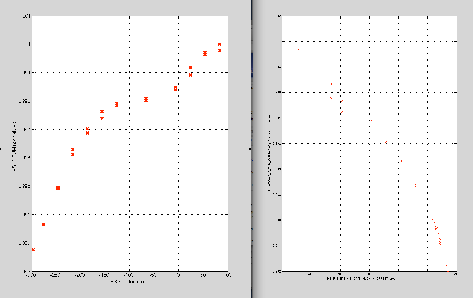
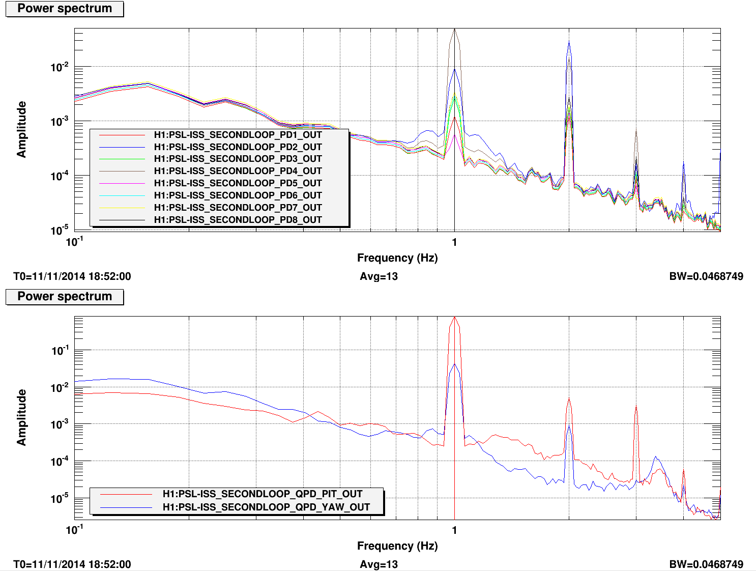
In the first attachment, the plot on the left is AS_C_SUM normalized VS the BS Y slider value (while the ASC loop was acting on SR2 to center AS_C). The scan started from Y=-296.5.
As the BS Y was increased, at some point PIT feedback on SR2 became large and eventually railed the SR2 BOSEMs, and that's probably why the plot shows a kink at around BS Y=0. I had to stop the scan at BS Y=83.5. During this scan BS BOSEMs never railed. Though it's not shown here, I also scanned SR3 while using the same SR2 feedback to center the AS_C, and the data also showed similar kink.
The plot on the right is a similar plot for SR3 scan. Note that these data were taken on a different days, so the laser power could be different at sub-% level, and the IFO alignment could be substantially different, but you can see that the two plots show the same kink.
Based on the above, I'd guess that the reason why SR2 had to be moved in PIT despite YAW scan is because the centering on SRM or SR2 was poor in PIT. (Remember, ROC of SR2 is -6.4m and that of SRM is -5.7m.)
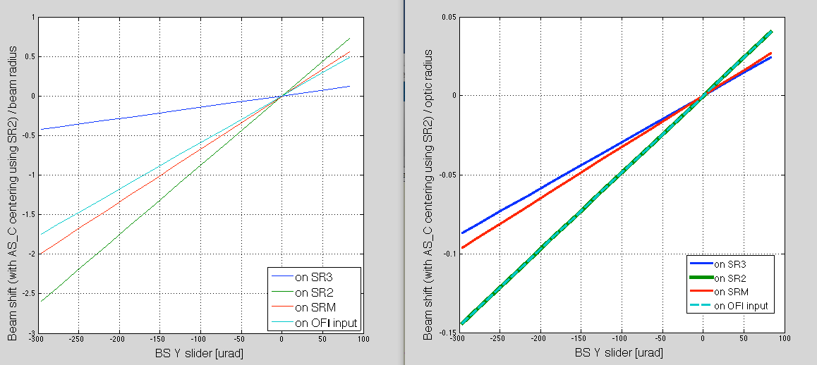
In the second attachement, I just plotted the beam displacement for the BS scan at SR3, SR2, SRM and OFI input normalized by either the beam radius (left) or optic radius (right), taking into account the fact that ASC is keeping AS_C centered using SR2. This doesn't prove anything, but suggest that SR2 and OFI are kind of dangerous as far as the clipping by the beam motion is concerned in this measurement, and we don't have to worry much about SR3.
(Note: The reason why AS_C should be centered is because the centering affects SUM number at sub % level.)