david.barker@LIGO.ORG - posted 07:44, Friday 26 September 2014 (14163)
CDS model and DAQ restart report, Thursday 25th September 2014
no restarts reported
no restarts reported
As preparation for automating the initial alignment, I did some things associated with the X arm locking.
(LSC-TRX_A_LF path was realgined at ISCTEX)
After the PSL light was locked to the X arm, I realigned TRX_A_LF path in order for LSC to be able to do triggered lock acquisition. The beam was already hitting the center of the bottom periscope mirror from the beginning. I steered the bottom periscope mirror and some optics in the down stream. I found that a lens had been taken out presumably due to the previous QPD work in this past July (see alog 12672). There was a post holder and a base plate secured on the table in front of the bottom periscope mirror. Looking around, I found a 2 inch lens (PLCX-50.8-515.1-UV-1064) with a post laid on the table. So I inserted it to the post holder and looked this was the right lens as the beam nicely converged towards the photo-diode (Thorlabs PDA100A).
Also, I put a temporary steering mirror aside. This is one of the mirrors that Sheila placed in this past July (alog 12672) and has been blocking the PDA100A. The DC voltage coming out from the PDA100A was about 300 mV with a 00-mode transmitted light on it. I did not check the gain setting of the PDA100A. The ADC count reached 1x10⁴ cnts when the arm was locked on a 00 mode. Probably we will need to decrease the gain of the PD or that of the interface box at some point in the future in order to aviod saturation.
In addition, I adjusted the trans camera. I needed to move a black-place beam dump closer to a beam splitter which is the one before the PDA100A. Then I steered the beam splitter and the angle of the camera to coarsely center the beam in the view. I could not identify the channel number for this signal at the video matrix in MSR. Looks like channel #53 is it, but it keeps flickering for some reason and therefore hard to tell. Though, a 00-mode beam was visbile ocasionally. We need to fix this in the day time tomorrow.
(IM4/PR2 alignment with REFL9 WFS)
Instead of aligning IM4 and PR2 by hand, I started doing it using the REFL WFSs. I used REFL_RF9_A and _B and they worked well. Once I zero-ed the electronics offsets in the RF9 demodulated signals,they started looking reasonable. I closed two loops by feeding the A_RF9_I signal to IM4 and the other to PR2. IM4 turned out to be a well-diagonalized actuator in the sense that it was able to actuate mostly on the WFS_A signals. On the other hand, PR2 had some cross-coupling which is not surprising at all. I need to work on this a bit more in order to have more diagonalized servos. I did not precisely adjust the gains. So these are the remaining tasks.
Anyway, closing the loops increased the transmitted light and reduced first-order coupling from angular fluctuation of some optics. Note that I had the DC centering servo running in order to keep the spot centered on both WFS_A and _B.
Baffle PDs, now with the correct labels:
| TMSY | ITMY | ETMY | |
|---|---|---|---|
| PD1 | (-69 PIT, -71 Yaw) | (165, -105.3) | (62, -77) |
| PD4 | (-149.5 PIT, -2 Yaw) | (197, -139) | (91, -40) |
| centered | (-109.25, -36.5) | (181, -122) | (76.5, -58.5) |
Especially in pitch, these are rather different from what we found yesterday, which is not too suprising since we were hitting the ITM somewhere far from the center yesterday. There is a beam at the end station coming back from the ITM, and some fringing at ISCT1. To be continued....
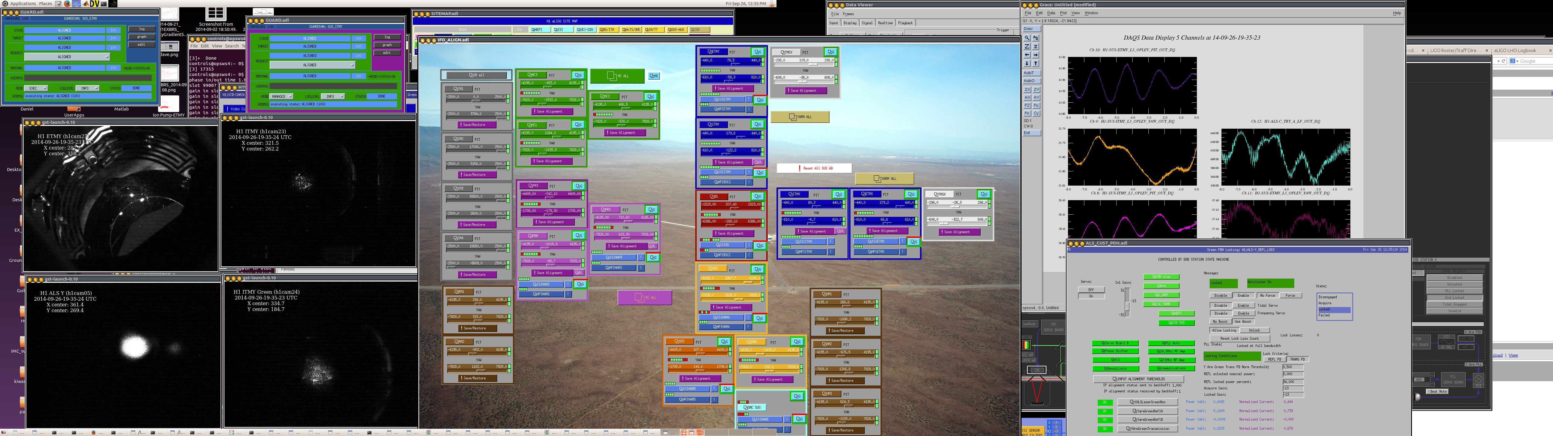
The Y arm is locked on green. This morning I tried to focus all the ITM cameras, I still had some difficulty but the images are much better than before kiwmau adjusted the gains. We also changed the sign on the TMSY alingment slider gain, it is now -158.
This means that the PIT values in all of our past alogs will now be wrong by a minus sign. It also means that TMSY now has the same sign convention as all the other suspensions for pitch.
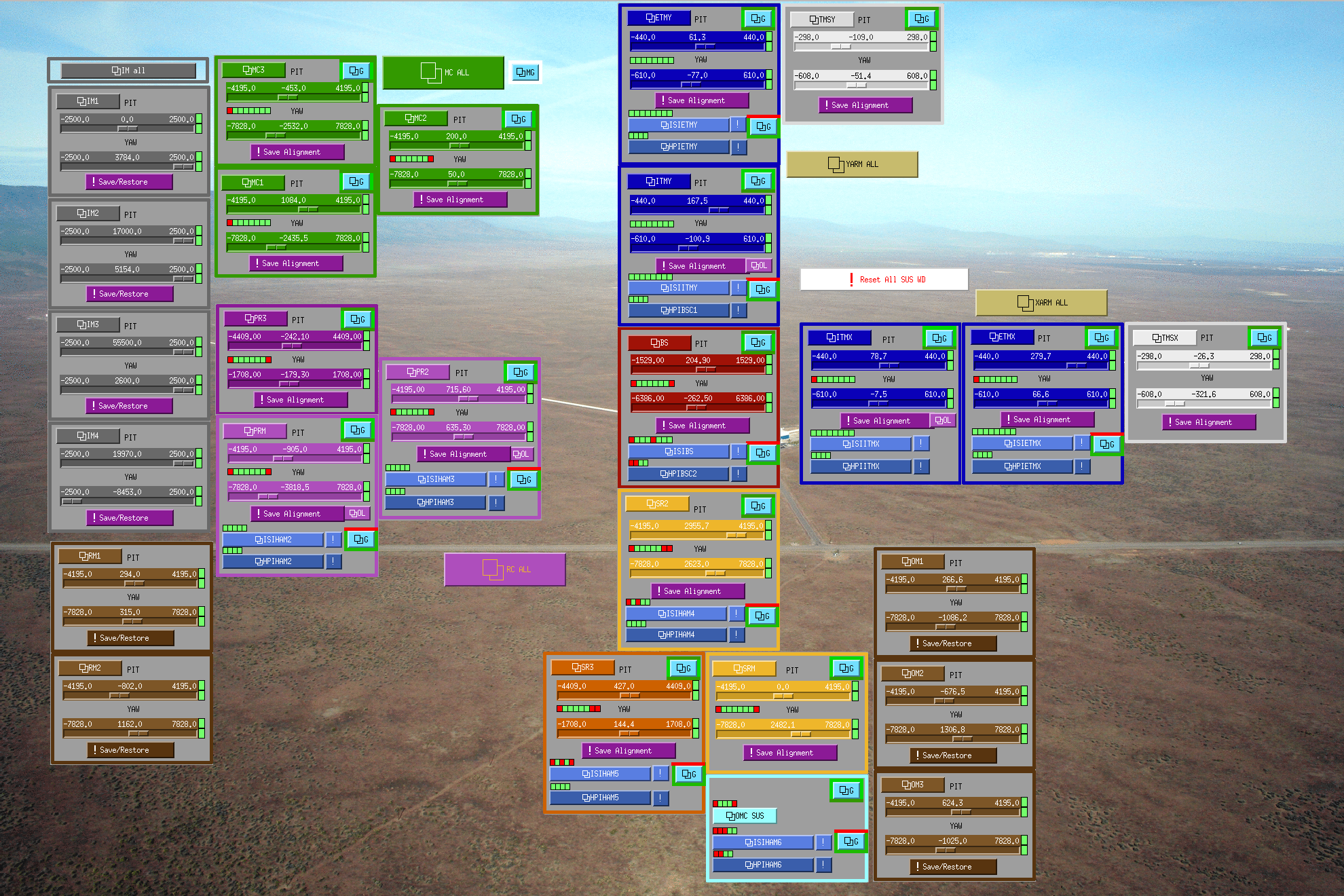
The atached screen shot shows the camera images, alignement biases, and beckhoff settings with green locked in the Y arm (although there is still a significant amount of power in higher order modes).
Note:
We only changed the slider sign because it was convenient.
However, if the BOSEM output should be consistent with Euler coordianate system, TMSY BOSEM input matrix and output matrix should be changed and the slider sign should be brought back.
Sheila, Kiwamu
We reconfigured most of the GigE cameras such that the analog gain is set to a high value in order to make the process of finding green light easier.
Now green beams as well as objects are quite visible on the cameras. For example, see the attached images below:
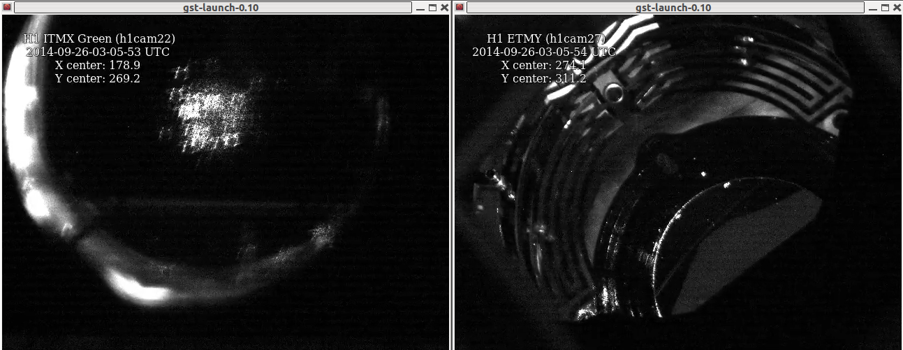
The camera image on ITMX looks similar to what Livingston has and therefore I am satisfied with the high gain setting.
(some details)
Sheila and I were having difficulty finding green light in most of the GigE cameras and therefore we had been wondering why they were not as sensitive as those in Livingston.
Looking at the camera initialization files in /ligo/cds/lho/h1/camera/ , we found a type which had been preventing the camera servers from changing the analog gain in its initialization process. In order to set the analog gain, the line should start from 'Analog Gain', but the line in all the files started from 'Default Analog Gain'. So we took out the 'Default' and reconfigured the servers by pressing the 'reload config' button in the medm screens. Due to this typo, all the cameras had been set to a default low gain regardless of what gain were requested in the file. According to the camera code (see camera_server.py in svn), the default analog gain is 100. We increased most of the camera gains to 1023 which is almost 10 times higher than they used to be. I am not sure if this is the highest, but certainly this was the largest number I saw among those files. In addition, changing the gain to some other higher value did not apparently make it brighter. So I guess that it should be already at the highest or close to the highest value.
Additionally, we found another typo in the initialization file: 'Default Exposure' should be 'exposure' according to camera_server.py. We fixed both typos in all the existing files.
Peter K, Sudarshan, Gabriele
As stated in the previous alog entry, we finally understood the cabling of the picomotors, and we checked that we can move all the four axis of the two ISS motorized mirrors.
We managed to get a beam on the QPD, with a total sum signal of about 12000 counts. Since the transimpedance should be 100k, this corresponds to something like 100 uW, which is even more that what we expect from 10 mW in input of the ISS array. So we are quite confident that we have the real beam on the QPD.
However, we still don't see much power on any of the eight photodiodes. The signal is something of the order of 5-6 counts at maximum for some of the diodes. Moving the picomotors while trying to keep the beam on the QPD didn't help much.
Searching for the maximum power on the photodiode is made difficult by the lack of a real DC output: the present board has a -20 dB gain at DC, rises with a first zero at 6 mHz, to about 60 dB at 10 Hz. This means that any transient in the power impinging on the photodiodes will easily mask the improvement we should get if the beam pass over the photodiode too fast.
So we modified the signal acquisition: using a DB9 break box we directly wired the test points after the transimpedance to the ADC, skipping the whitening. This modification has been implemented for PD1,2,3,4.
Moving around the picomotors we could finally get a beam on two photodiodes: PD1 sees something like 0.2 mW and PD3 something like 0.15 mW. This is still much lower than the expected ~1 mW per diode. PD2 and PD4 see some signal, but much smaller. We don't know what's happening to PD5-8, since they're still acquired with the whitening.
In this position, the beam is not hitting the QPD.
Aidan. Greg.
I fine-tuned the alignment of the ITMX HWS probe beam this afternoon. Actually, I'm now getting a return beam from ETMX, which I don't want, so I'm a little too close to a perfect retro-reflection. I'll detweak it tomorrow.
The camera has also been moved close to the conjugate plane of the ITM HR surface.
All of this was done with the LEXAN cover on the viewport. Further refinement will be necessary when this is removed. It should also clean up the return beam image.
The ITMX return beam is shown here. You can see the normal shadow from the baffles and the earthquake stops. There are no noticable stray beams coming from anywhere else.
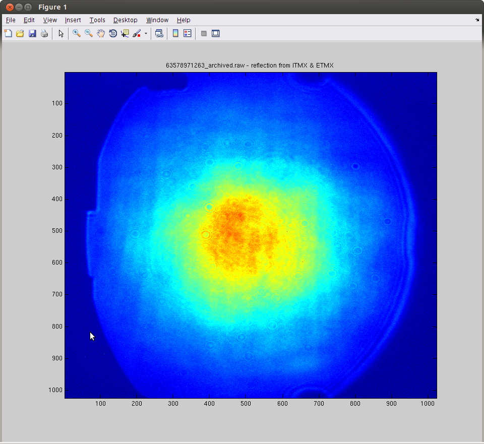
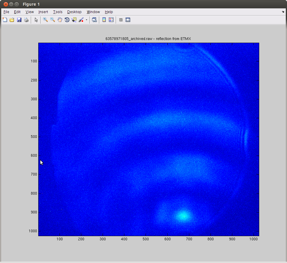
I also misaligned ITMX to prevent the return beam getting back. Here's the return beam from ETMX. I know this is from ETMX because it swings back and forth when I put an injection into ETMX YAW.
LVEA is Laser Hazard

08:21 Hugh – Running transfer functions on HAM6 HEPI
08:52 S. Sachder – Going to End-Y to check PEM microphones
08:54 Danny – LVEA west bay to work on 3IFO Quads
09:06 Filiberto – Cabling ISS Array Picomotor (PM5) to HAM2 feed-through
09:15 Travis – LVEA west bay to work on 3IFO Quads
09:33 Karen – Cleaning at Mid-Y
09:42 Richard – Working on cabling for PM5 at HAM2
10:00 Adian – Going into the LVEA
10:15 Cyrus – Going to all outbuildings to property tag equipment
10:15 Betsy – LVEA west bay for 3IFO Quad work
10:51 Richard – Going to LVEA to work on cameras with Filiberto
12:58 Danny – LVEA west bay to work on 3IFO Quads
13:15 Travis – LVEA west bay to work on 3IFO Quads
14:15 Greg – Attaching flex tubing between HWF and HAM4 viewport
15:17 Sheila – Focusing cameras on both X & Y arms
15:42 Adian – Working on flex tubing installation at HAM4
All auto running under guardian, watchdogs if you please--H
Gabriele, Peter K., Daniel, Sudarshan
From our capacitance measurments (LHO: alog 14148), and the cable specification drawings: D1000581 and D1101515, we concluded that the picomotor on HAM2 are connected to the following channels:
Channel Picomotor
1 ISS (PM1-closer to the array)
2 IM4 Transmission QPD
3 Faraday Half Wave Plate
4 IMC Input Pointing
8 ISS (Before the telescope)
5, 6, 7 Empty
This is consistent with the channel assignment at LLO alog 12174
During the process we moved the Faraday HWP (Channel 3) and IMC Input Pointing (Channel 4) quite a bit, but we brought it back to its original position, atleast on theory. We moved these the same number of steps back as we moved forward and viceversa. :)
Picomotor code and wiki updated to reflect the revised motor assignment.
With the last TF data section taken last night, ran through the scripts to load generic controllers. They closed no problem. I believe troubles before were related to changes in the local to cartesian matrices. Started the Guardian node and if functions fine.
Attached is a before and after spectra plot. It looks like there is some increases with the loops closed on vertical dofs around 0.7 to 3hz but the broad peak at 4+hz is reduced. The ISI has only damping loops.
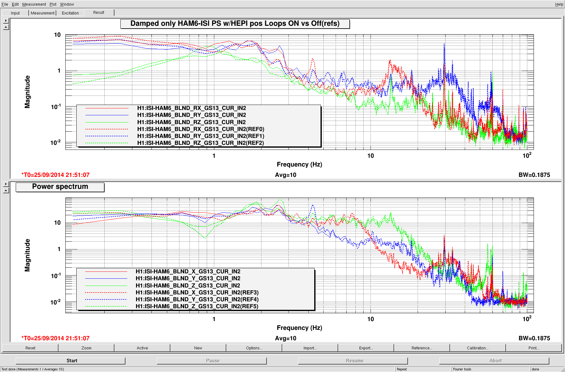
Safe.snap made.
Gabriele, Peter, Sudarshan
We tested the picomotor 3 (supposedly ISS H1) and 5 (supposedly ISS pickoff) using the picomotor test setup and did not see any signal change in the StripTool window except for the 3X channel. 3X channel showed some increase in signal amplitude but would settle back down after the drive was complete.
We measured the capacitance across each pair of connector and got the following results:
1X: 209 nF (J1: 1-14) 5X: 4.0 nF (J2: 1-14)
1Y: 208 nF (J1: 2-15) 5Y: 3.9 nF (J2: 2-15)
2X: 211 nF (J1: 3-16) 6X: 3.9 nF (J2: 3-16)
2Y: 212 nF (J1: 4-17) 6Y: 3.9 nF (J2: 4-17)
3X: 217 nF (J1: 5-18) 7X: 3.9 nF (J2: 5-18)
3Y: 4.3 nF (J1: 6-19) 7Y: 3.9 nF (J2: 6-19)
4X: 201 nF (J1: 7-20) 8X: 211 nF (J2: 7-20)
4Y: 211 nF (J1: 8-21) 8Y: 211 nF (J2: 8-21)
1, 2, 3X, 4 and 8 has picomotor connected
3Y, 5, 6, 7 are empty
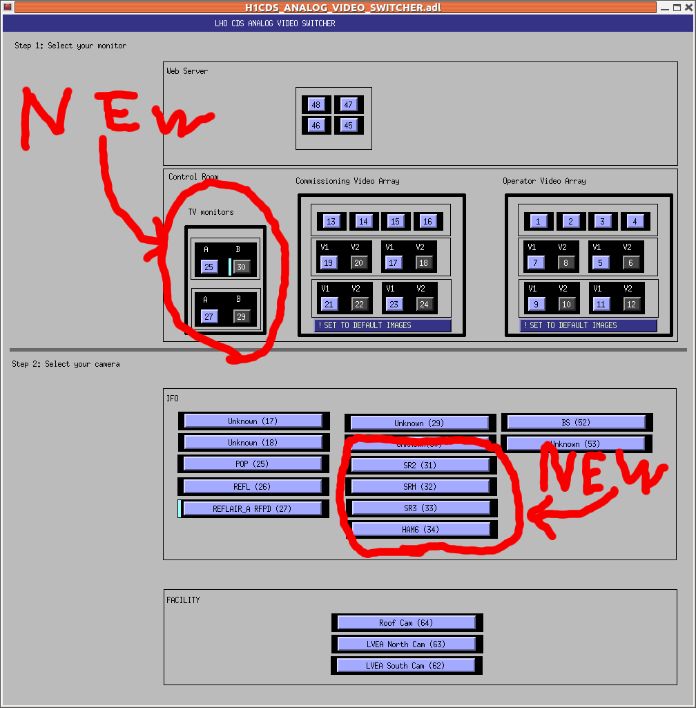
We can now monitor the SR mirros and also can use the TV monitors as outputs. See the attached:
Summary of the activities from the last night:
Below are some details:
(X arm locking)
The PSL light was locked to the X arm by feeding the signal back to MC2. This configuration gives us a situation where we can steer IM4 and PR2 such that the input pointing matches the cavity axis of the X arm. In prior, I moved the bounce and roll filters in MC2 from ISCINF to M2_LOCK_L such that the notches are applied only to the M2 stage. This is a suggestion from Ryan of LLO in order for a HSTS suspension to avoid ringing up the modes without sacrificing the length control bandwidth. This seemed to help the stability a lot. I did not see a too-prominent peak at these bounce and roll frequencies when it was locked. Good.
I followed the procedure described in a previous alog (alog 13747) except for the sensor. This time I used ASAIR_RF45_I instead of a REFL detector because ASAIR seemed to have a larger signal level without extra whitening amplifications. Also I tailored the demodulation phase to -98.6 deg which maximized the in-phase signal. The LSC gain needed to be 0.01 in this case which gave a UGF of 50 Hz. Measuring the open loop transfer function, I found that the phase margin at around the UGF was about 10 deg or so. So I put a lead filter in FM5 of LSC_XARM to bring the phase up by approximately 30 deg around the UGF. The measured open loop with the lead filter on is attached below.
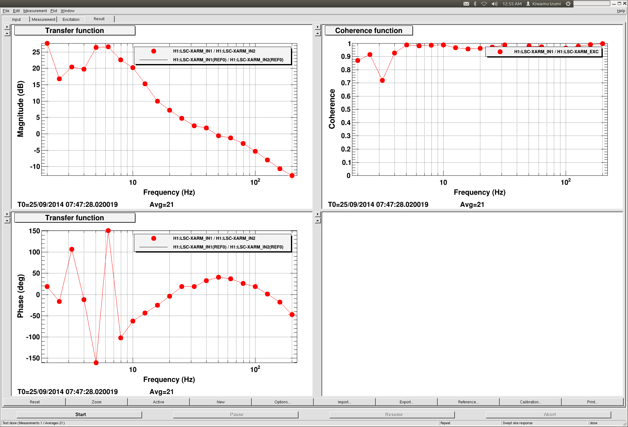
Though, I still don't understand why the phase had been so bad in the first place. According to the digital filters we have, the phase between 40 and ~200 Hz should be about 90 deg as it falls as 1/f. But the open loop looked falling as 1/f2.
(POPAIR realignment)
After I touched up IM4 and PR2 (mainly in pitch), I could not get reasonable signals from both POPAIR_A and _B at all. I went to ISCT1 and checked the beam in the path. Indeed the beam was off from both diodes. Similarly to the other day (alog 14055), I could not precisely evaluate the beam position on the top periscope mirror. The beam was too high on the bottom periscope mirror while the horizontal looked centered. I steered the top periscope mirror and realign the down-stream again. Also, I moved the POP camera position to a point close to the last steering mirror in order to get a bigger beam image.
After the realignment, I did not see an apparent sign of clipping in the POP beam image. Good.
(Michelson free swing)
See the attached below:
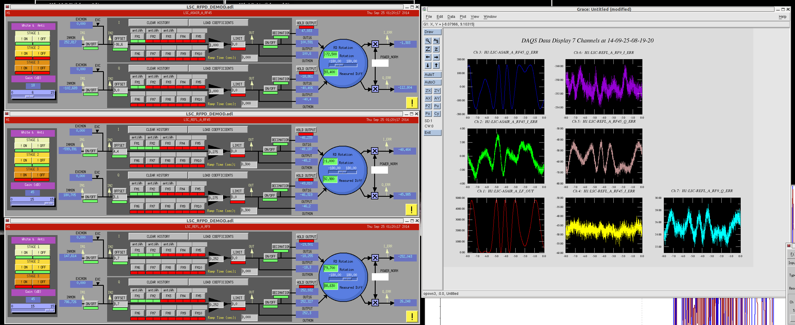
Note that the incident power on IMC at this point was 10 W.
Daniel and I have found that the optical lever sign convention for ETMs and ITMs was changed in May/2013, and now it's opposite of what I remember.
I'd like to know why it is/was a good idea.
Right now, the dot on the screen goes up when the OL beam goes down.
It probably was changed so that the convention matches the SUS coordinate system so that positive pitch in the OSEMS should read positive pitch in the OLs, if this isn't the case then it's an error.
Keita, Sheila, Gabrielle
Now, in chronological order:
result of TMSY to IMTY baffle PD search:
|
PD label in epics |
PIT | YAW | V | gain (dB) |
| ITMY PD1 | 2.2 | 7.3 | 3.6 | 20 |
| ITMY PD2 | -72.5 | -70 | 4.3 | 20 |
| ITMY PD3 | -153.5 | -1.6 | 20 | |
| ITMY PD4 | -97.8 | 74 | 3.6 | 20 |
Based on D1200657-v4, (assuming the view shown is looking at it from the BS), this does not make sense with the arrangement of baffle PDs. These votlages are low compared to what we see on the X arm, so we suspected that this was a second bounce or ghost beam, however, they do not move when the ITM or ETM are moved, so they are not reflections off of those optics. If we think that if these are the real beam, the baffle PDs are mislabeled somewhere, so we used the TMS suspension alingment sliders to try to figure out which PD is which. (Unfortuately, the TMS alignment slider also seems to be wrong.)
Based on our reinterpreation of the labels, we thought that the beam should be roughly centered on the optic when TMS is at -35 PIT, -31 Yaw. However, we saw no sign of our beam at this location, nothing on ISCT1 and nothing returning to the ETM when we scan the ITM. Keita trended the old values, and we saw the beam go by on SRM when he restored them. Gabriele and I went to ICT1, and found a badly clipped beam by exciting the BS. Later Keita and I returned and moved the TMSY alignment to get a somewhat better beam, with a TMS alignment of -87 PIT and -51.4 YAW and BS at 187 PIT and -258 YAW, we have 10 uW on ISCT1. this was the same in the spring (alog 11296) giving us some confidence that we really have the single shot beam on ISCT1. (This is our first clue that the TMS alingment slider is wrong)
We went through the baffle PD game by moving ITMY and looking at the ETMY baffle PDs, using this TMS pointing which isn't necessarily centered on ITMY:
| PD label | PIT | YAW | V | gain (dB) |
| PD1 | 140 | -106 | almost 2V | 20 |
| PD2 | 112 | -135.9 | 2 | 20 |
| PD3 | 140.3 | -170 | 2 | 20 |
| PD4 | 173 | -140 | 2 |
20 |
This seems to make sense, but the power is low again. We think this beam should be roughly centered on the ETM with the ITM slider at 156.5 PIT -123 Yaw.
Since exciting the ETM (around its saved alignment) and watching on the MC1 camera and at ISCT1 didn't show us any return beam, we redid the baffle PDs for the ETM pointing:
| PD label | PIT | YAW | V | gain (dB) |
| PD1 | 11.3 | -26.3 | 0.17 | 0 |
| PD2 | 42.0 | -60.4 | 0.21 | 0 |
| PD3 | 72.3 | -26.6 | 0.17 | 0 |
| PD4 | 48.5 | 8.8 | 0.18 | 0 |
This beam also did not make sense with the baffle PD arrangement, or our interpretation of the actual PD arrangement based on the TMS alingment sliders. This means that either ETMY or TMSY has a sign flip in the pitch alignment slider (our second clue):
| label | reality according to TMSY | reality according to ETMY (I think this is the correct case) |
| PD1 | PD4 | PD2 |
| PD2 | PD1 | PD1 |
| PD3 | PD2 | PD4 |
| PD4 | PD3 | PD3 |
Once we understood this I decided that our ETMY interpretation of the cabling must be the correct one, since the TMS pointing that actually gets a beam through the optic is very different in pitch than the pointing we calculated based on the baffle PDs. Using this information, our original TMSY centered pointing should have been -113 PIT, -35 Yaw. Indeed, this pointing does result in a beam that doesn't look clipped on ISCT1. I can also see two other beams on ISCT1 which come from the ETM, but haven't been able to easily align the arm cavity. Although I see some fringing, the mutliple bounce beams seem to get clipped as I try to align them. I think the next step is to start fresh with baffle PDs, now that we think we know which one is which.
The root of the sign flip for TMSY is the transition from H2 to H1.
H2 TMSY used to have the same sign convention as the H1 TMXS as far as the bias sliders are concerned.
However, when it was moved to new H1 TMXY position, the top cage needed to be rotated by 180 degrees. This changed the PIT sign convention but not YAW.
See D0900419 (H2 TMSY) and D0902168 (H1 TMXY).
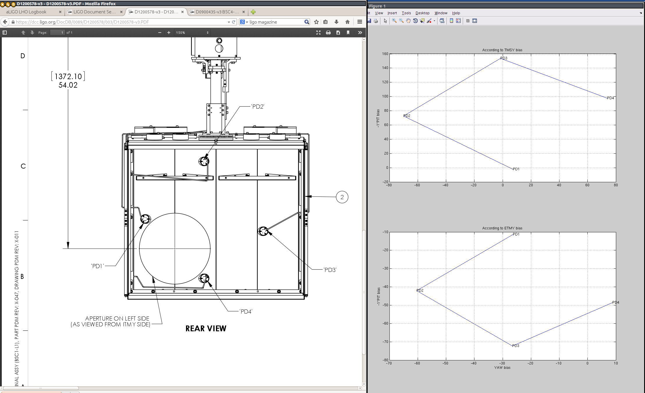
For your convenience, the attached is the relative position of the ITMY baffle diodes viewed from the ITMY according to the TMSY and ETMY slider bias.
To the left of the plot is the drawing of the said baffle viewed from ITMY (D0900435).
ETMY plot (bottom plot) agrees well with the drawing assuming the cross cabling mentioned by Sheila. If you flip the TMSY plot vertically it also agrees with ETMY and the drawing.
Now I've swapped tha cables at the baffle PD amplifier box, so the labels should be correct. For the record I swapped PD1 and PD2 cables, and PD 3 and PD4 cables. This is what we think will give correct labels in epics, based on the ETMY alignment sliders.
QUAD 06 (Q6) Phase 1B transfer function plots are attached. We had a hard time obtaining good coherence in the Transverse TF, so it is a bit hashy. Will try again.
Most notably is that, like Q8, the second pitch mode frequency is unexpectedly pushed upward on the main chain. Recall, we never found the mechanism to fix it on Q8. Interestingly, both the Q8 and Q6 assemblies are of the same batch of wires and are fresh builds, but by 2 different assembly teams, and on 2 different solid stack/test stand units. Q8 is an ETM type of QUAD while Q6 is an ITM QUAD, but both main chains have the same pendulum parameters - both are detailed in the 'wireloop' model.
The Q6 data is plotted as QUADTST.
We've checked that all wire diameters are as per the specs and that the wire segment clamps are seated properly on the masses. We've also checked that the wire segments have been assembled with the proper assymetry as per specs (looking for something obvious).
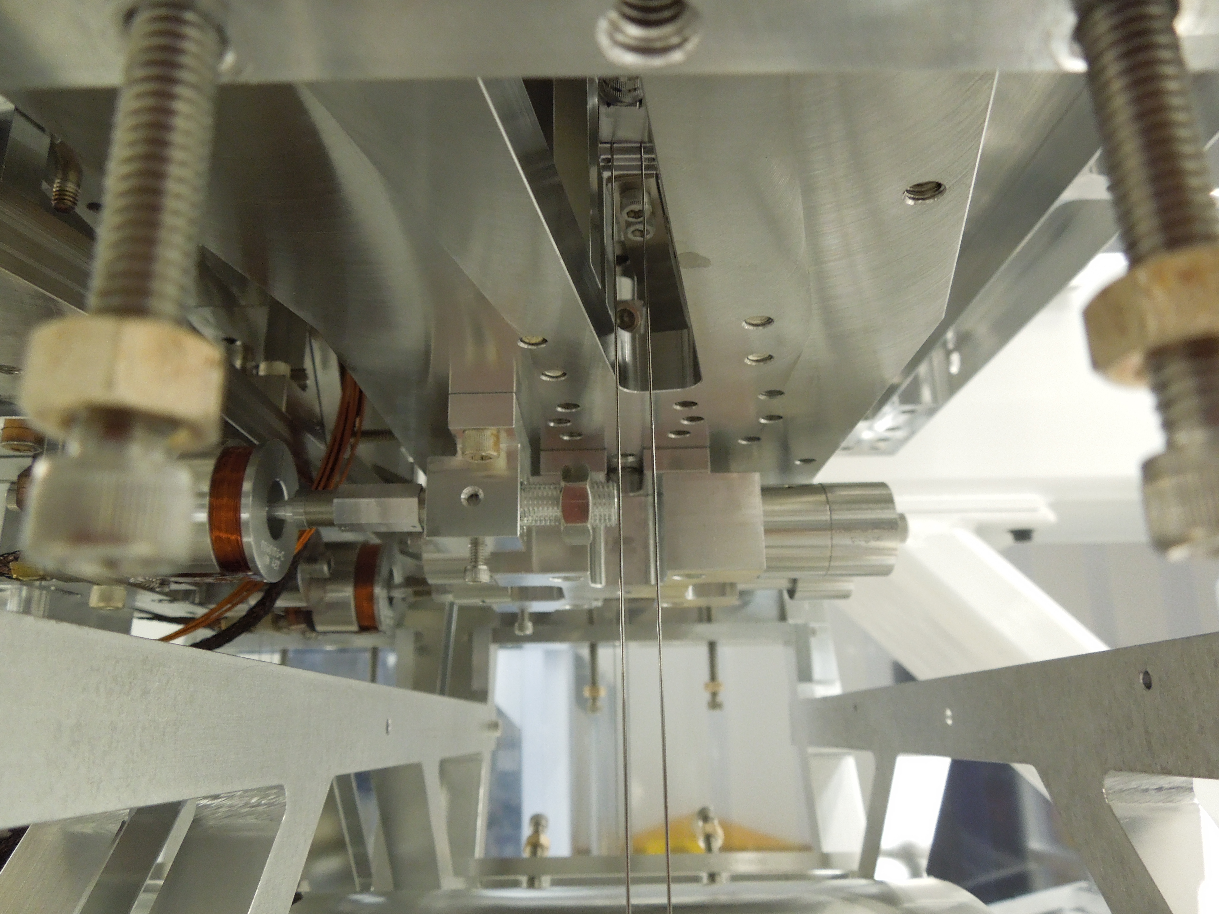
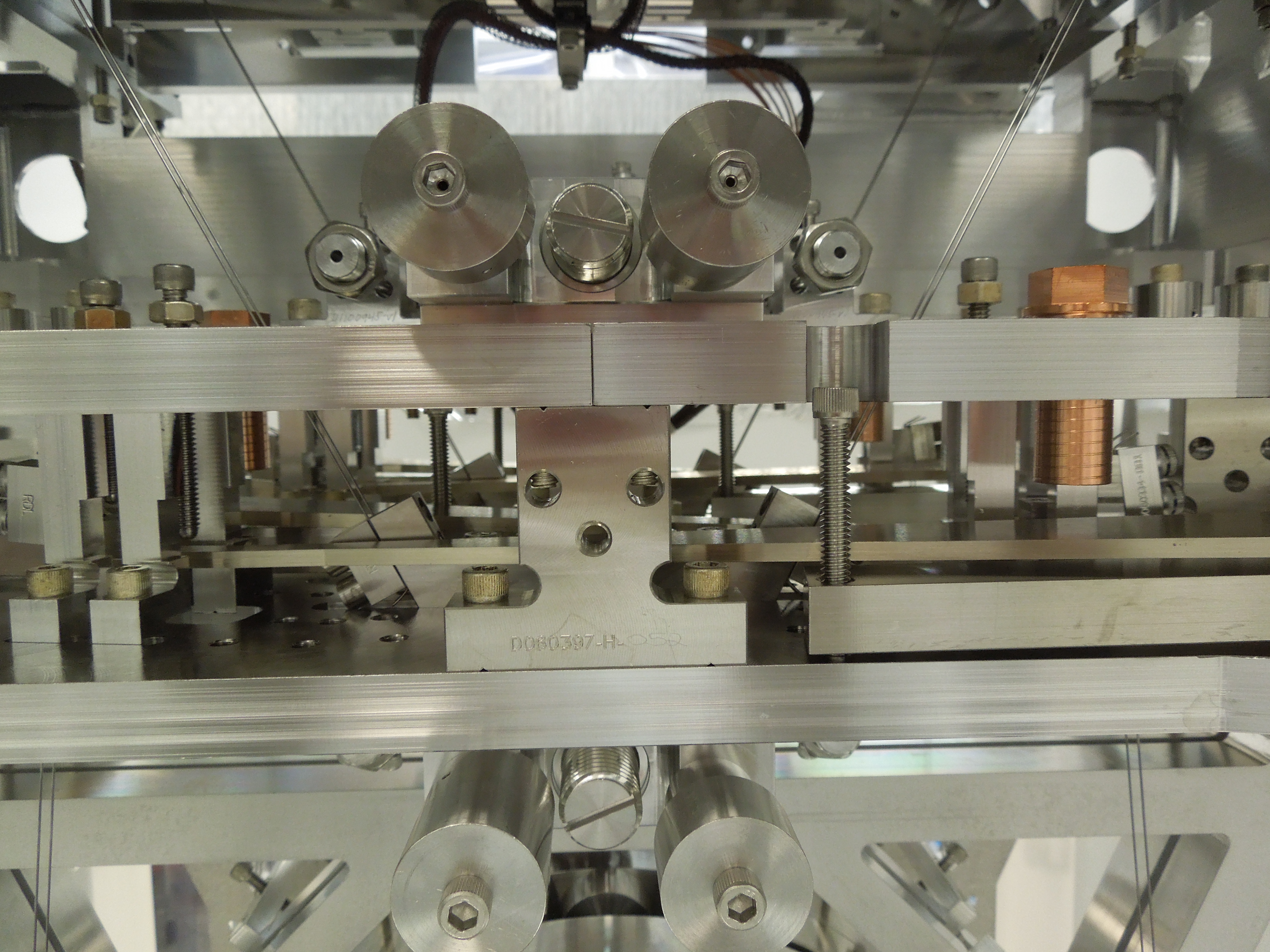
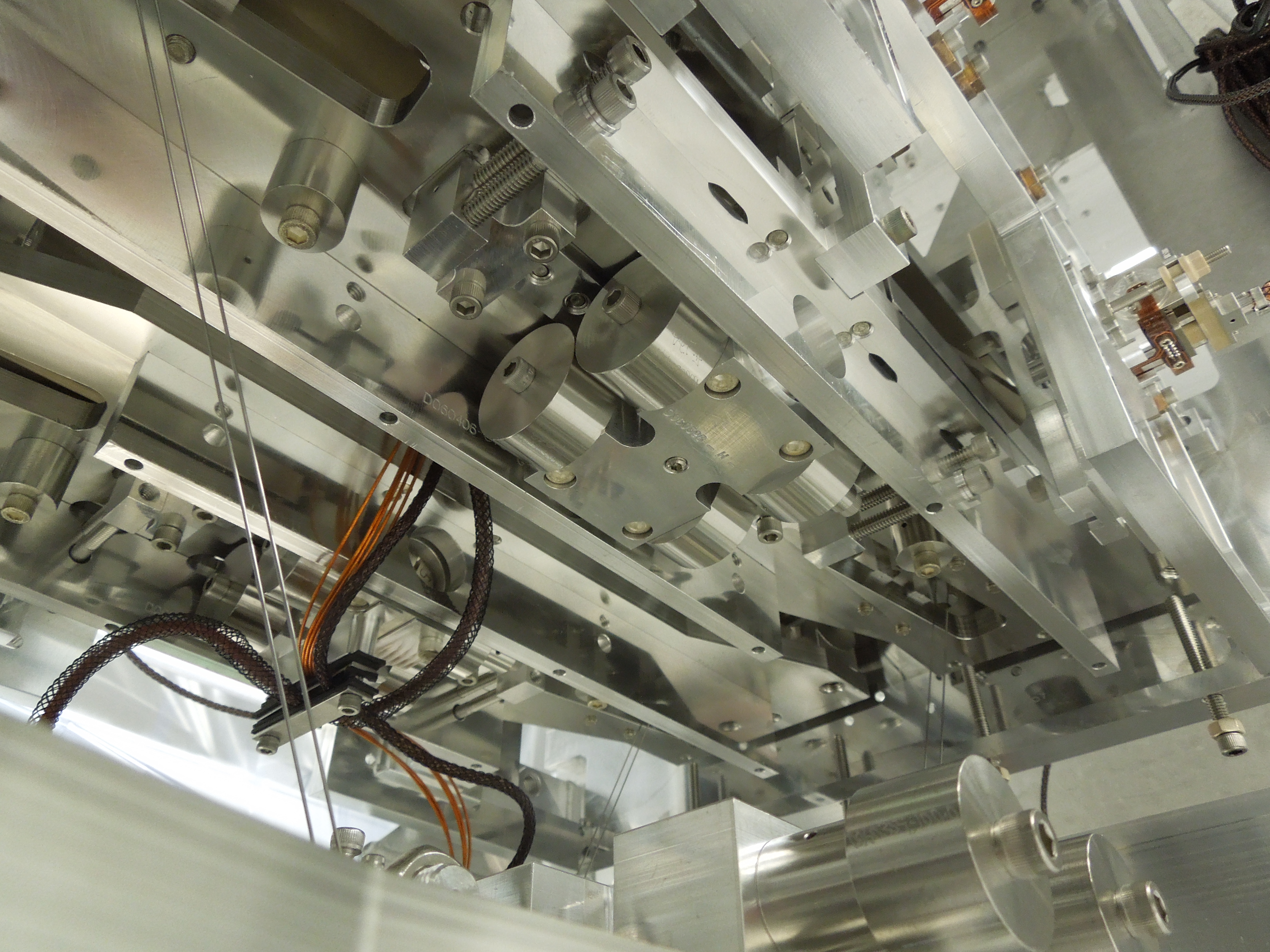
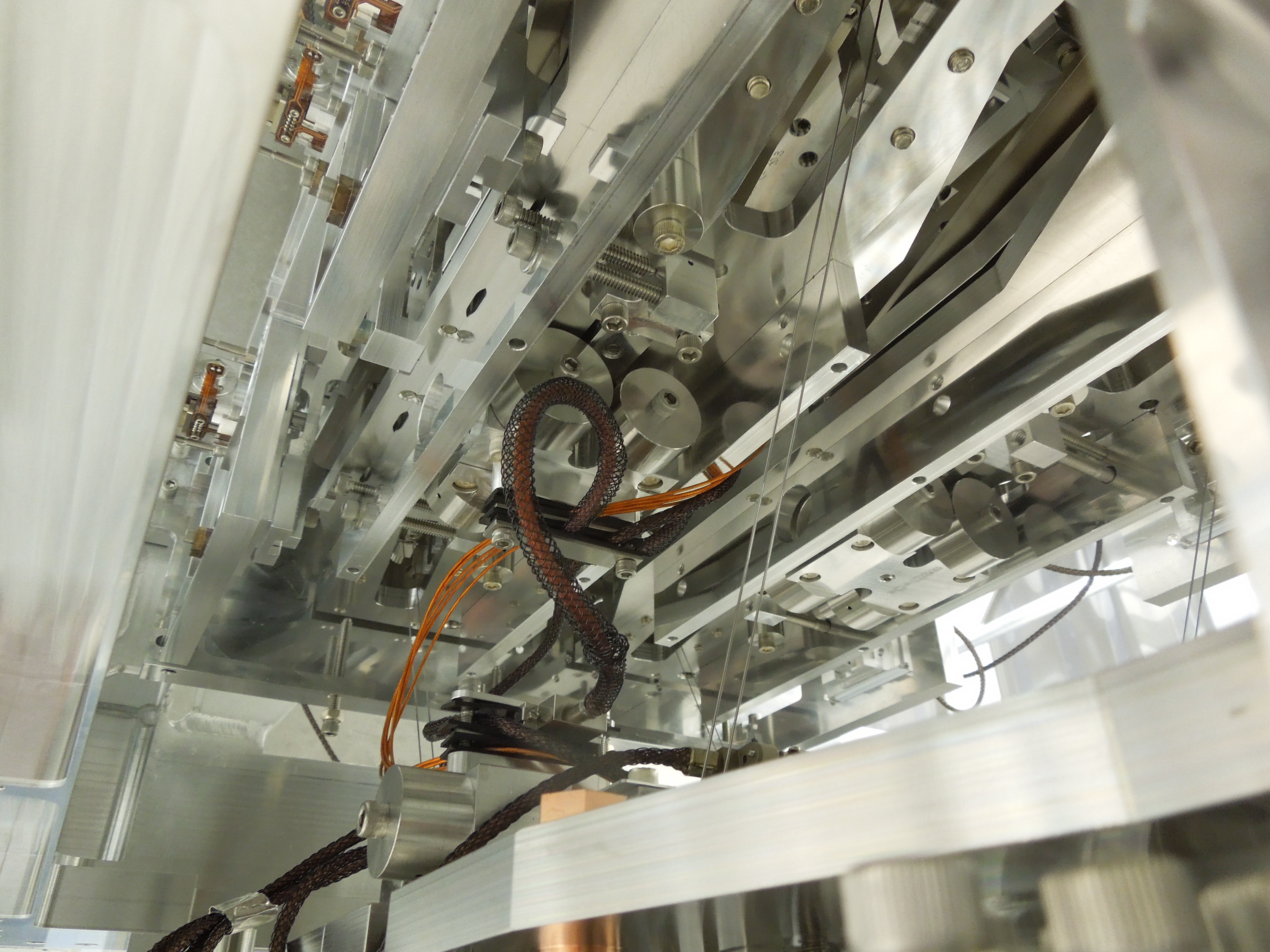
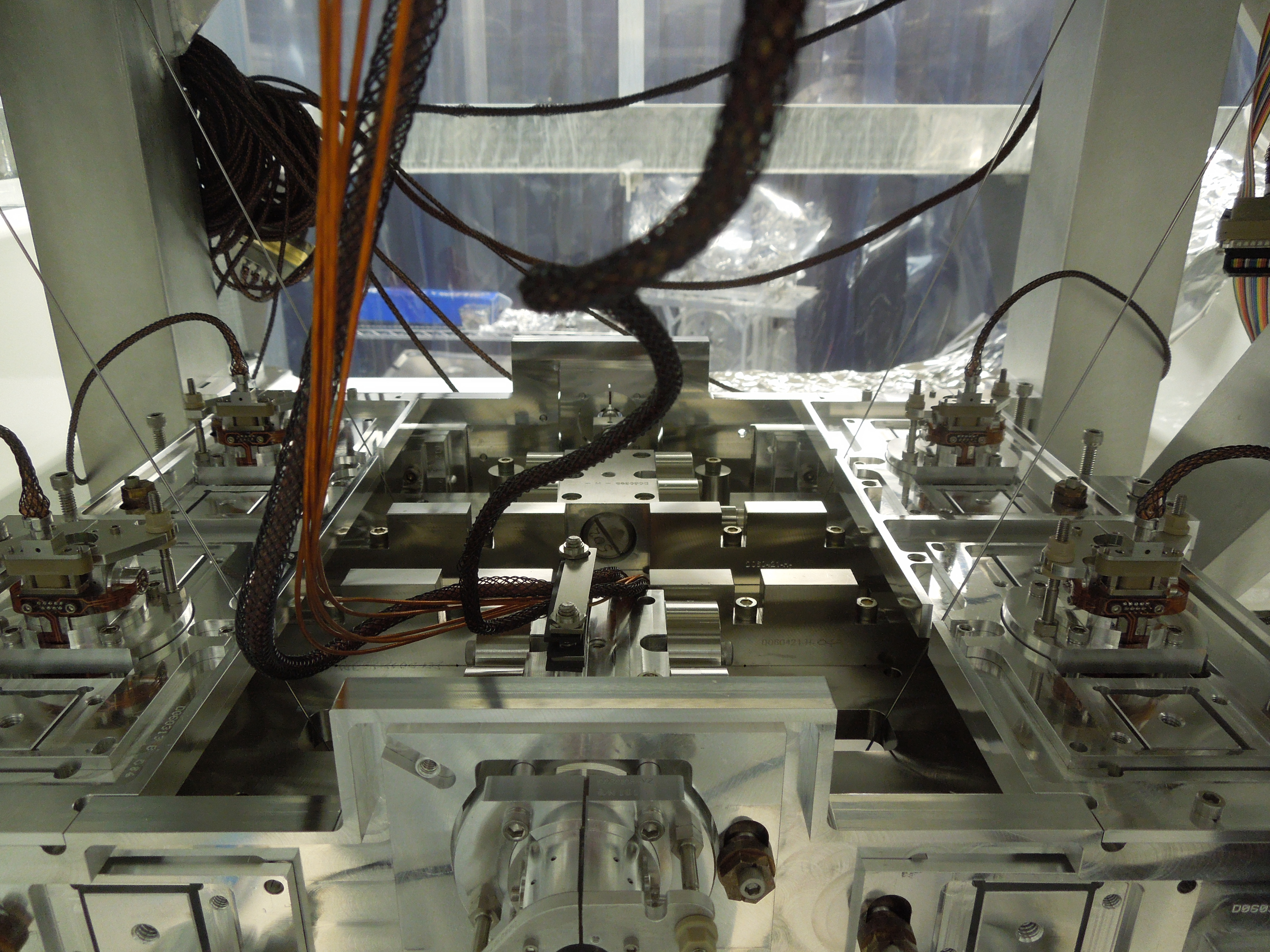
Attached are pix of this unit, in case someone wants to look at them. To me, they look just like the last few QUADs we've built, including Q8.

Maybe this is a long shot, but we've exhausted all the simple causes...could the top wire be the wrong material? If the modulus of elasticity was higher, within a factor of 2 from where it is supposed to be, that would explain this strange pitch mode.
One way to test this is to measure the violin modes of the topmost wire in situ and see if it is right. Or maybe more simply, cut some wire from this wire stock, hang some wieght off of it, and measure its violin mode.
The correct 1.1 mm diameter wire should have a violin mode of
frequency in Hz = sqrt(tension/0.0067)/(2*L)
where 0.0067 is the mass per unit length.
For example tungsten has a modulus about 2 times higher than what we are supposed to have. If for whatever reason we ended up with a tungsten wire, it would have an in-situ violin mode in the low 200s of Hz, rather than the 332 Hz spec (much denser than the usual piano wire).
Or even more simply, you could weigh some length of wire. The piano wire should be something close to 7 g/m. If you get different value from that, then the wire is the wrong material.
To confirm Brett's latest suggest regarding the wrong wire: We have 2 rolls of 1.1mm diameter top wire here at LHO which could have possibly been used for QUAD builds. Both are labeled as the correct stuff. We weighed a 1m segment from each spool. One measures 7.1g, the other measures 7.3g.
To be continued...
Another sanity check:
The Top Mass blade sets used for these 3 pitch-problematic QUADs are as follows:
Q6 - SET 10
Q8 - SET 8 - although I can't find the actual records
Q9 - SET 2
Q7 - SET 7 - still to be tested, unknown pitch frequency TFs
The SETs go from SET 1 being the most STIFF to SET 16 being the most SOFT. So, the sets we are using for the 3IFO QUADs are somewhat scattered or in the middle of the pack. They are not all clustered at the soft end, nor all at the stiff end...
And here's the spectra of this Q6. Note, the lowest stage (L2) does not have flags during the all-metal Phase 1 assembly, so the spectra plots of L2 are junk.
And now attached are a damped TF from each R0 and M0. As we all have noted in SUS - damped TFs on Phase 1 test stands are not useful since the damping is a function of the code on the out-dated test stands and the loops are not tuned very well. Long story short, there is a little bit of damping evident, given whatever filters and gains are loaded, and we can see healthy excitations run through the suspension so all seems well with damping capabilities of Q6.

Fil looked at the situation of the X arm trans camera. The bad flickering view went away after we power-cycled the video receiver/transmitter. He thinks that the AC adaptor maybe the one causing the issue. We will keep eye on it.
By the way, now we are confident that video channel #53 is the X arm trans.