david.barker@LIGO.ORG - posted 07:50, Tuesday 04 November 2014 (14821)
CDS model and DAQ restart report, Monday 3rd November 2014
no restarts reported
no restarts reported
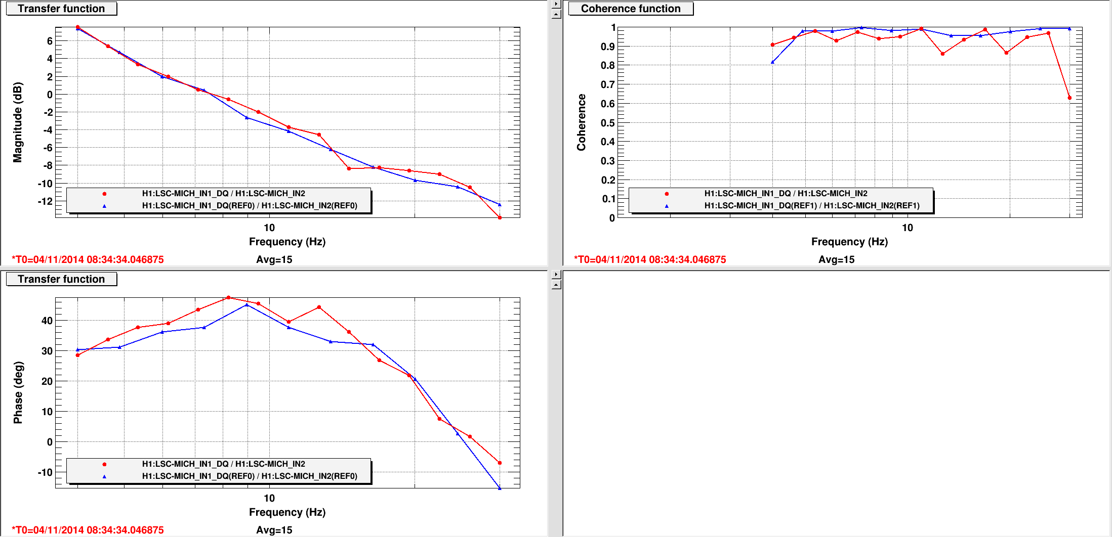
As an exercise to test out the OMC --> LSC signal path, I locked the simple Michelson using the OMC-DCPD_SUM signal. With MICH locked on a dark fringe with a 35 count offset, I measured the DCPD-to-MICH transfer function. The DCPD sum was a factor of ~4 smaller and off by 180deg at low frequency, so I loaded "-4" into the LSC input matrix (OMC DC --> MICH) and zeroed the ASAIR_RF45 element. The lock was very smooth, with about 2x more gain than the vanilla MICH loop. (I found the guardian-set gain the MICH_DARK_LOCKED state was about 3x smaller than maybe it should have been, so I increased it from -500 to -1400 before the handoff. After the handoff I reduced the gain to -700. The UGF with these settings was ~7.5Hz, roughly aligned with the peak of the phase bubble.)
Comparisons of the OLTF in both states (with the gain settings described above) are attached, so are noise spectra for the error and control signals. In both plots the references are the RF lock, current signals are the DC lock.
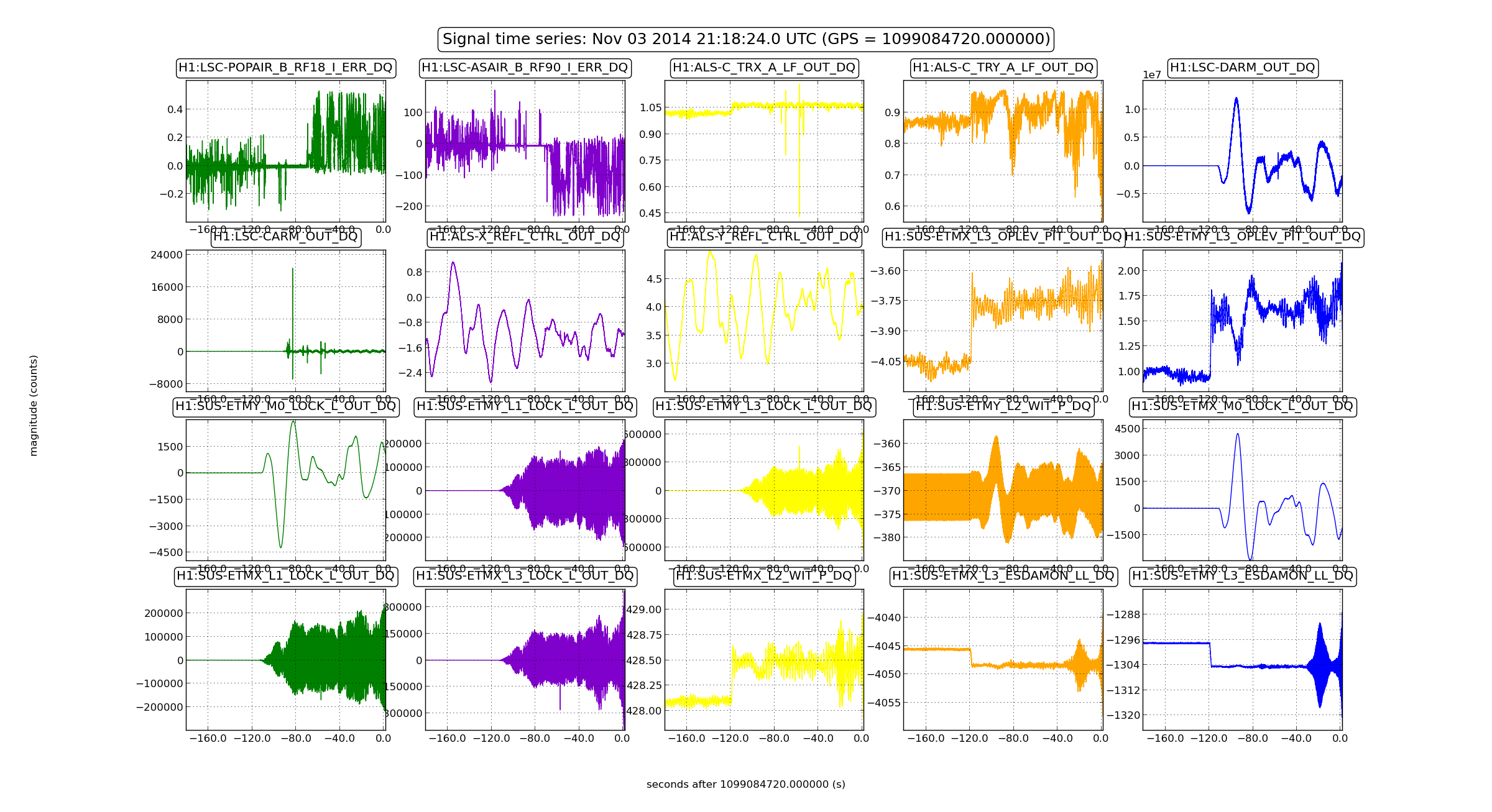
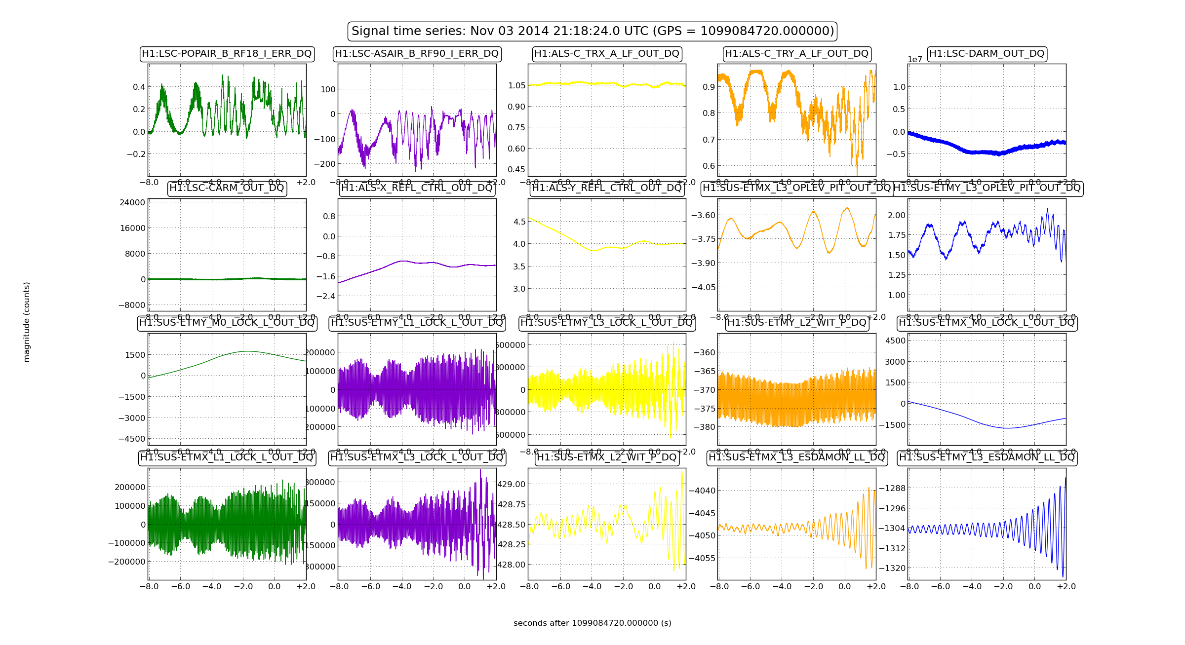
Alexa, Evan, Sheila, Jeff, Nic, Lisa

The plan for tonight was to try again the CARM offset reduction with the DRMI locked on 3f as it was done  a few nights ago .

However, sadly, we couldn't really stably lock the arms on green by engaging ALS DIFF (feed-back to the ETMs).

Nothing was (at least intentionally) changed with respect to the "nominal" configuration which has worked in the past.

In the process of collecting and analyzing several lock losses, we identified the following list of problems/action items:

 * L2P for ETMY is significantly worse than for ETMX, we should fix this: as soon as the differential feed-back to the ETMs is engaged, the ETMY green light fluctuates consistently with PIT fluctuations as seen by the optical lever. This effect was really bad in the afternoon (30% power fluctuations; it got somehow better later in the evening);

 * ringing up of the 13 Hz ETMY roll mode (again, see Kiwamu's entry): Nic tried to damp this mode by using optical lever PIT as error signal and pushing on L2 PIT, but that didn't work. We will try tomorrow to use the  LLO strategy  by using ALS DIFF;

 * at least once we lose lock because of a 3Hz oscillation in the ESD drive (we should remeasure the cross over L1/L3).

While trying to debug the ALS, we did some work on the DRMI to investigate the tricky demod phase business (see  Evan's entry).
We had tried feeding back only to ETMX ESD, to remove the large 13 Hz peak in the ALS DIFF spectra. We had done this in the past, but we could not get it to work. At one point, I also tried adjusting the L3 LOCK L gain in case the ESD charge had changed the crossover. However, not surprisingly this did not make a difference since the ALS DIFF spectra did not show any gain peaking at the crossover frequency.
These are some plots which show the problem described in this entry (13 Hz roll mode oscillation and 3 Hz loop oscillation in bad alignment state, L2P filters worse for ETMY than ETMY). It might be worth checking if the ground / ISI motion was somehow higher than usual last nigh for the arm cavity optics.

P.S.: In the process of doing some lock loss analysis, I realized that our new awesome lock loss tool  didn't like empty lines in the channel configuration file. I think this explains while Sheila et al have been observing unexplained script failures when trying to add more channels (by the way, the max number of channel per file is 20). Nic fixed this problem in this way, now it works well.


def load_channel_list(path):
    channels = []
    with sys.stdin if path == '-' else open(path, 'r') as f:
        for line in f:
            # skip empty lines
            if line.isspace():
                continue
            channels.append(line.strip())
    return channels
Nic and I briefly entertained the idea of going out to the end stations to optimize the gain and whitening on the ETM oplevs, but decided (based on the attached spectra of the segments) that it was good enough for today's oplev work.
Alexa, Sheila, Lisa, Evan
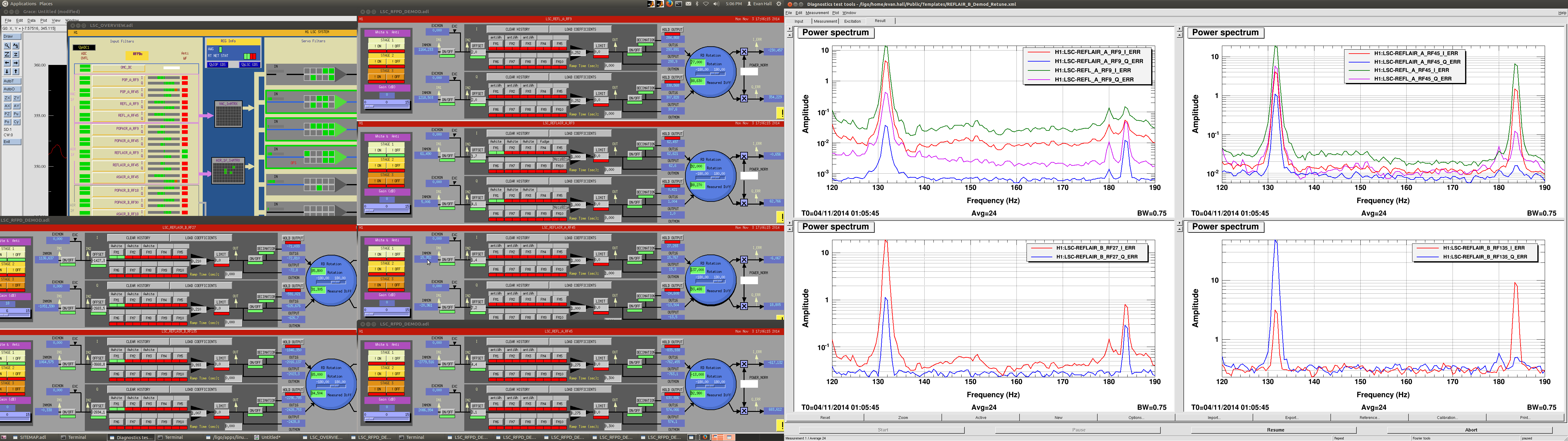
Today we looked a bit further into the demodulation issues we've been having with the DRMI sensing matrices (see 14792).
Using the same technique as described in LHO#14792, we measured the response of REFLAIR_A and REFLAIR_B (along with REFL_A) while driving PR2 and SR2.
We ran at 10 W into the IMC, with no ND filter on any of the diodes. Excitations were 131.7 Hz and 6000 counts on PR2, and 183.8 Hz and 6000 counts on SR2. At one point, we also tried exciting PR2 at 211.7 just to make sure our results were the same (and they were).
While monitoring the PSDs of the RF-demodulated diode signals, we tuned the phases as follows:
The attached plot shows the RF-demodulated diode signals after this retuning. Our conclusions are as follows:
The DTT file for this measurement is at /ligo/home/evan.hall/Public/2014/11/REFL_Tuning/REFL_Tuning_Spectra.xml.
Alexa made sure that there was no clipping or any other funny business with REFLAIR_B.
We briefly tried to take a measurement at a lower input power, but could not keep DRMI locked.
For reference, the original demod phases are as follows:
Dave [WP#4929] new models for h1calex, h1caley. Same functionality, split code into a common library part. May install h1calcs on h1oaf0 if the specific_cpu assignments can be verified for this front end. DAQ restart is required.
Dave: Reconfigure EDCU for latest Beckhoff and resync to guardian. Restart DAQ.
Jeff K, Stuart A: possible SUS model optlev changes, DAQ restart required.
Dave: recompile h1lsc against older version of RCG to fix slow-data-channel-offset-in-daq problem which was reintroduced last week
No other work planned.
They are not 'prepared' yet but that is but a moment. So this uses TF data from 4 Sept 2013 but with the correct Local <--> Cartesian matrices. Additionally, these are Hugo's Generic Controllers in use already on HAMs 4 5 & 6; we'd like to use these where ever we can. Otherwise I attach them here if you wish to look at them. A few of the dofs have phase margins less than 30; but, our problem at EndX had only 20 degrees of margin.
I plan to 'prepare', load , and test them tomorrow morning.
9:00 Bubba to LVEA measuring cleanrooms
~10:58 Rai and Kyle to EY removing ionizer setup
12:00 Rai and Kyle back from EY
1:00 Cris and Karen to MX and MY respectively
1:45 Karen leaving MY
Alastair
The flipper mask holders are installed on the X and Y tables. Both are cables up and working using a 'caput' command. At the moment they won't work using the MEDM screen since this requires checking the state of the flipper (up/down) using sensors that are not yet on the table.
Final outstanding intstall work is : X-table needs 1 flipper sensor. Y-table needs 2 flipper sensors, FLIR camera and baffles around PDs.
The difficulties with H1 DRMI locking, and with getting H1 to full lock, prompt me to survey the top level configuration differences between H1 and L1.
Some other comparisons that should be made (not in the table) are:
At this point we don't know which of these differences, if any, are significant for the lock acquision. Please post comments to this entry if you have some ideas on this, or if there are other known differences that we should be looking at.
| parameter | L1 | H1 | comments |
|---|---|---|---|
| input power for locking | 2 W | 10 W |
|
| modulation depths, 9/45 MHz | 0.25/0.29 | 0.19/0.28 |
not sure if L1 values are current |
| ETM global feedback | hierarchical | distributed |
|
| SUS local damping | A | B |
They're different; see G1401267; Jeff K and Stuart A are working on comparison plots |
| DRMI ASC servos | 4 loops | 3 loops |
BW probably lower on H1; more complete comparison needed |
| HSTS feedback & coil drivers | increased M2 drive for PRM & SRM | increased M2 & M3 drive for all HSTS | |
| LSC servo loops |
comparison needs to be made |
||
| 3-f PD photocurrent (DRMI) | 0.15 ma | 27 mW -> 3 ma |
H1 has done limited trials with a reduced photocurrent |
| WFS centering loops |
different, but comparison needed |
||
| ALS ETM feedback | ? | Done when needed to bring frequency in range | |
| Michelson contrast defect: modeled, no arms, no TCS | 6400 ppm | 10,800 ppm |
SIS model, using as-built ITMs |
| Modeled power recycling gain: carrier, no arms, no TCS | 40 | 33 |
SIS model, using as-built ITMs |
RF spectra from the 3-f BBPD have been posted to both LHO and LLO logs recently, so here is a comparison of those.
LLO data: log 15430 , photocurrent: 0.21 ma
LHO data: log 14807 , 27 mW -> inferred photocurrent: 3.0 ma (better would be a direct measurement of photocurrent)
Comparison of 6 highest RF peaks:
| Frequency | L1 | H1 | Delta |
|---|---|---|---|
| 9 MHz | -41 dBm | -11 dBm | +30 |
| 18 MHz | -29 dBm | -12 dBm | +17 |
| 36 MHz | -18 dBm | -1 dBm | +17 |
| 45 MHz | -30 dBm | -12 dBm | +18 |
| 54MHz | -25 dBm | -6 dBm | +19 |
| 90 MHz | -33 dBm | -14 dBm | +19 |
Other than 9 MHz, the BBPD output RF components on H1 are all about 20 dB higher than the corresponding components for L1. This is about what is expected from the higher photocurrent used on H1 -- in fact we'd expect closer to 24 dB, if the inferred H1 photocurrent is right. The 9 MHz on H1 is another 10 dB higher (on top of the 20 dB), which is odd considering that the f1 modulation depth on H1 is smaller. This may indicate that on 3-f locking, there is more of an offset on PRCL (or MICH?) in H1 than L1, or maybe more residual motion.
In any case, L1 can hold a stable DRMI lock with the lower 3-f signal level, but H1 has not been able to so far. The LLO log entry also included demod error signal spectra for the DRMI. I'm hoping someone at LHO can post a comparison of that with the H1 situation.
A reminder that at 2am PDT, the clocks went back one hour to 1am PST. This means the hourly autoburt wrote out two "1am" sets of data, the second one overwriting the first. This can be seen if we look at a GPS time channel in one of the snap files. There gap between the midnight entry and the "1am" entry is 7198 seconds, or 1.999 hours.
Also remember local time is now UTC - 8hr
00:10/h1nds0epics.snap:RO H1:DAQ-NDS0_GPS 1 1.098947755000000e+09
01:10/h1nds0epics.snap:RO H1:DAQ-NDS0_GPS 1 1.098954953000000e+09
02:10/h1nds0epics.snap:RO H1:DAQ-NDS0_GPS 1 1.098958553000000e+09
03:10/h1nds0epics.snap:RO H1:DAQ-NDS0_GPS 1 1.098962155000000e+09
Adjusted REFSIGNAL from -2.02V to -2.06V to bring diffracted power down from ~12% to ~10.8%.  I am hesitant to make more aggressive adjustments since last time I did, Rick was surprised that such large adjustments were required.  Further investigation?


Laser Status:
SysStat: Warning “VP program online” is red
Output power is 29.4 W (Should be around 30 W)
FRONTEND WATCH is active
HPO WATCH is red

PMC:
It has been locked 5 days, 21 hours, 58 minutes.
Reflected power is 2.0 Watts and PowerSum = 25.4 Watts.
(Reflected Power should be <= 10% of PowerSum)

FSS:
It has been locked for 15 hour, 22 min.
Threshold on transmitted photo-detector PD = 2.20 V (should be at least 0.9V)

ISS:
The diffracted power is around 10.8% (should be 8-10%)
Last saturation event was 1 hour, 34 minutes ago
Morning meeting:
Commissioning:
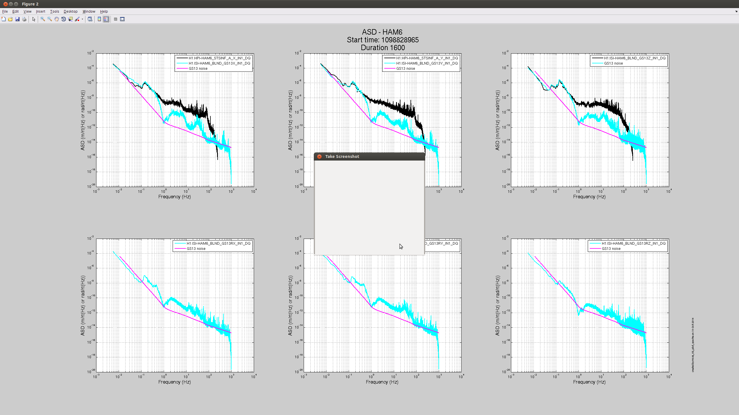
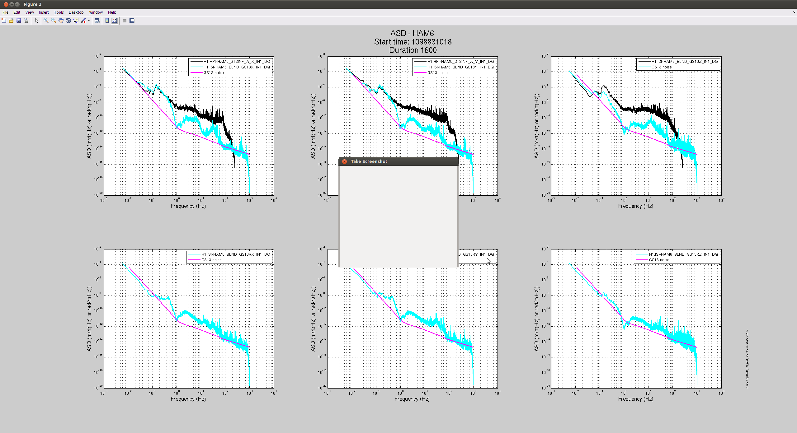
No commissioners asked for this, but I was curious so I installed Rich's sensor correction filter on the HAM6 ISI. It looks like it does good things, but I've only tried Z so far. I don't really know if there are any optics or useful oplevs on HAM6, so I'll bug commissioners about what metrics they would use at that chamber to measure performance, but the ISI's own sensors show improved performance down to 100mhz and very little re-injection below that. First attached plot is before, second is after. Comparing the upper right plot on each shows the improvement. It's interesting that RX and RY also seem to be improved.
model restarts logged for Sat 01/Nov/2014
2014_11_01 15:27 h1fw1
model restarts logged for Sun 02/Nov/2014
One unexpected restart Saturday. No restarts reported Sunday.
I spent some time working on the ISC guardians today, in the hope that we could save ourselves alot of mindless clicking in the coming week. The users guide:
Now there is a generator for states where we sweep some channel and search for the transmitted light, which is used by both COMM and DIFF for a coarse then a fine sweep. This is slow but does work, and will be faster than doing it by hand. After COMM finds the resonance, it is now resetting the VCO set frequency, so that when the set frequency offset is 0, the arms are on resonance. However, there is some kind of a bug in the beckhoff that causes an error in the VCO after this. I will look into it tomorrow, since I try not to work on beckhoff on the weekends.
There is another bug, either in the IMC_LOCK guardian, the node manager, or the way that I am trying to use the node manager. When the IMC goes to its fault state (which usually happens because the FSS has dropped lock) it gets stuck there and won't move on. Dan pointed out that one difference between this and other transitions that seem to be working fine, is that the arrow goes from the fault state to INIT. We tried having it return 'INIT' instead of return True with an edge to INIT, this didn't work either (It got to down and just didn't move on from there).
I've added a goto state called bring_down_nicely to the DIFF guardian. The current DIFF down state gives the suspensions a terrible kick, I think this is not necessary.
The issue you're seeing with the managed IMC_LOCK node is the intended behavior of "MANAGED" nodes. When a managed node undergoes a jump transition, it goes into a "stalled" state whereby it waits for a new request from before proceeding along it's path. This gives the manager a chance to react and coordinate the actions of the subordinate with other subrodinates.
There are two solutions:
I've thought about this before, and I think there is a definite need to have a "watching only" manager mode that doesn't put the subordinate into MANAGED mode, but allows the manager to monitor it's progress with the same NodeManager interface. I'll work on adding that to the next guardian release.
Rana, Alexa, Sheila, Peter, Evan
Given last night's strange behavior from REFLAIR_B, we wanted to check the RF powers coming out the BBPD and going into the ISC rack.
With DRMI locked (on 1f, and then on 3f), we used the HP4395A to take an RF spectrum of the "direct" output of the REFLAIR_B diplexer board. This should be the raw RF signal out of REFLAIR_B, with 12 dB of attenuation from a coupler inside the diplexer.
The spectra (adjusted for the 12 dB coupler) are attached.
For 27 MHz, the power into the diplexer is -41 dBm. Using the diplexer schematic (D1300989), this should give -23 dBm at the diplexer's 3x output, which is well below the compression point of the amplifier (ZHL-500HLN+; 1 dB comprsesion occurs at +16 dBm). Similarly, for the 15x output we expect -13 dBm.
The analogous LLO measurement is at LLO#10494.
Power levels were as follows:
Dan remeasured the modulation indices (LHO#14801).
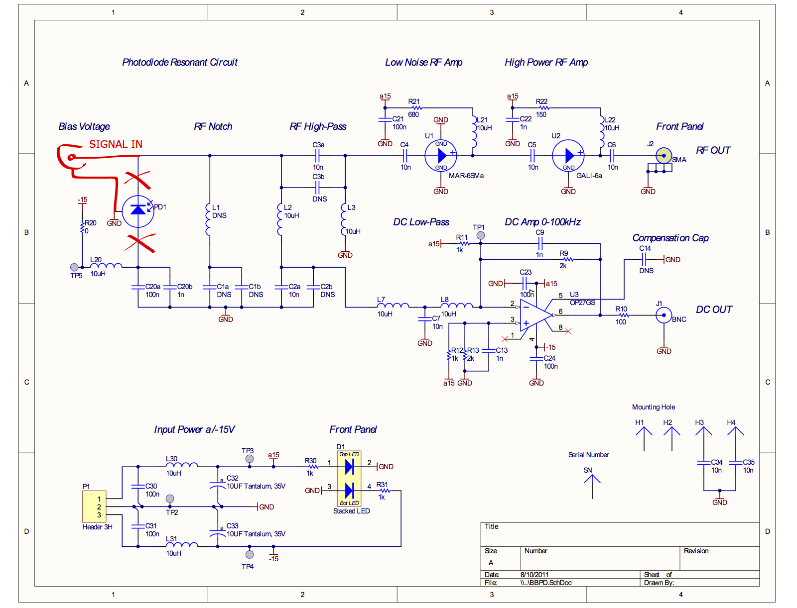
A quick estimate of the amount of distirtion in the BBPD amplifiers (MAR-6SM+ and GALI-6+):
The total amount of RF power in the attached spectrum is about +1 dBm (coming mostly from 4f1). Before the GALI-6+ in the BBPD, that's −11.2 dBm at the output of the MAR-6SM+.
The output-referred IP3 of the MAR-6SM+ is +18.1 dBm. Assuming the third-order distortion of the amplifier grows like the cube of the input power, this means the expected power of the third-order distortion is −11.2 dBm − 2×(18.1 dBm + 11.2 dBm) = −70 dBm out of MAR-6SM+. Then after the GALI-6+, the distorted power is −58 dBm.
[Koji, Rana]
The preamp chain of the BBPD was electrically tested. It turned out that intermodulation can explain the observed RF signals at 27MHz and 135MHz.
Method:
A spare BBPD at the 40m was used for this test.
The photodiode was removed from the BBPD circuitry and an SMA connector was soldered instead. (Attachment 1)
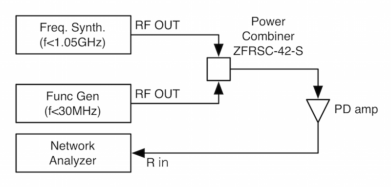
The measurement setup is depicted in Attachment 2.
The RF signals from two signal sources were combined with a power combiner and fed to the modified BBPD.
The output was connected to a network analyzer in order to monitor the output levels at each frequency.
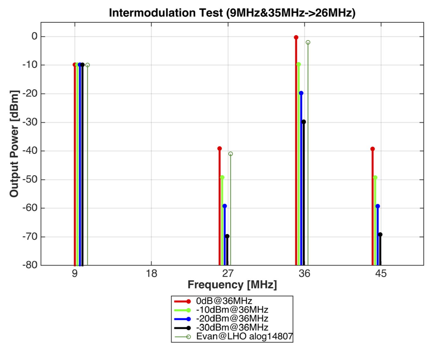
Measurement 1:
Firstly, Intermodulation produced from strong 9MHz and 35MHz components was tested.
WIth these two signals injected, our taget signals appear at 26MHz and 44MHz.
This way we can avoid the interference by the third harmonic distortion of the 9MHz signal.
The result is shown in Attachment 3. The 9MHz and 35MHz input levels were adjusted such that the output levels are -10dBm and 0dBm respectively.
These levels were obtained from the measurement in alog14807 (above).
It is clearly seen that symetric intermodulation appeared at 26MHz and 44MHz. The intermodulation level is linear to the level of the 35MHz signal.
In fact, -10dBm@9MHz and 0dBm@35MHz explain -40dBm@26MHz which Evan observed in the inlock spectra.
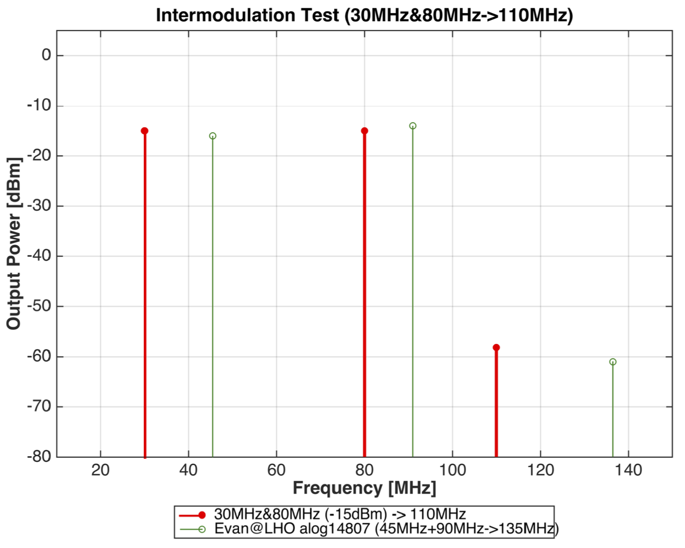
Measurement 2:
In the second measurement, it is tested if the intermodulation can produced enough amount of 135MHz signal.
Evan's measurement shows that both 45MHz and 90MHz have -15dBm.
From the lmitation of my setup, I had to use 30MHz and 80MHz to produce 110MHz, instead.
This indeed produced the 60dBm intermodulation, which is consistent with Evan's measurment.
Meaning of this measurement:
What happens if the intermodulation overwhelms the intrinsic signals at 27MHz and 135MHz?
- The intermodulation without fluctuation itself imposes unreasonable offsets in the 3f signals at DC.
- Power fluctuation of the sideband power in the 36MHz (f1-f2) or 91MHz (2xf2) causes unnecessary (=meaningless) signal to the 3f demodulated signals.
- The londitudinal IFO error signals in the 9MHz or 45MHz signals are imprinted to the 3f signals at a certain unknown demod phases,
and thus screw up the demod phase of 3f signals, as well as the immunity of them against the carrier audio sidebands.
Remedy:
- Lower the light power on the PD, if possible to maintain lock.
- Notch out/filter out unncesessary RF components before the BBPD preamps by adding components on the BBPD boards.
- Use resonant type photodetectors in stead of the broadband one to selectively amplify the desired lines.
This is related to Hugh's log 14774. To elaborate a bit on Hugh's log, I made a measurement with Stage 1 Damped only and HPI isolated. The first plot shows the GND_T240_X , ST1_T240_X and HPI L4C (out of loop witness). There was no coherence with ground below 0.1 Hz but there was significant coherence with HPI L4C. This meant that HPI was somehow introducing excess low-frequency motion.
We then did the same measurement on ETMY and saw no such excess motion. The second pdf shows the corresponding measurement. Stage 1_Y was very coherent with ground_Y. Jim mentioned he had modified the HPI controllers on ETMY as described in Hugh's log, so we decided to try the same on ETMX in X and Y.
This has made a significant difference to the low frequency performance of Stage 1 as shown in the third file. Performance below 0.1 Hz is much closer to ground motion now.
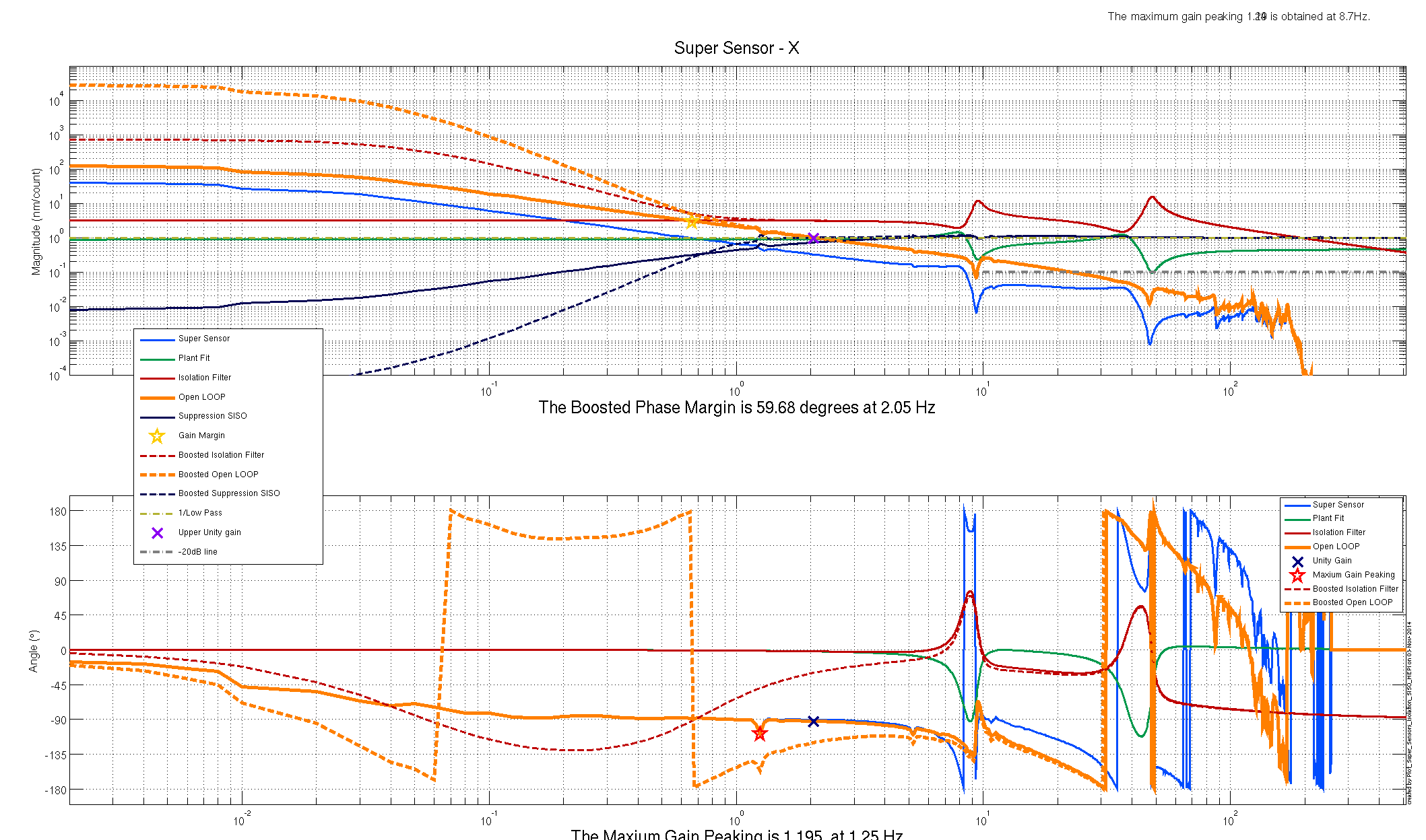
Some more plots of the old vs new isolation filters, per Jeff's request. I dug into the foton file to find numbers to back up what I thought the original design was. The gains of the old and new foton filters are shown in the first image, they show that not much was done to the filter design, just that the gain was reduced. Solid lines are the old design(higher gain, UGF), dashed lines are the current design. Second and third images are the currently installed plant design and a reconstruction of the orignal design (no plots were found from the original design from earlier this year). The solid and dashed orange lines tell most of the story, mostly we just cut the UGF to 2hz, and modified the boost to get more phase margin. No idea why this affect the very low frequency noise, Jeff and Krishna suggested maybe we were re-injecting IPS noise with the higher gain.
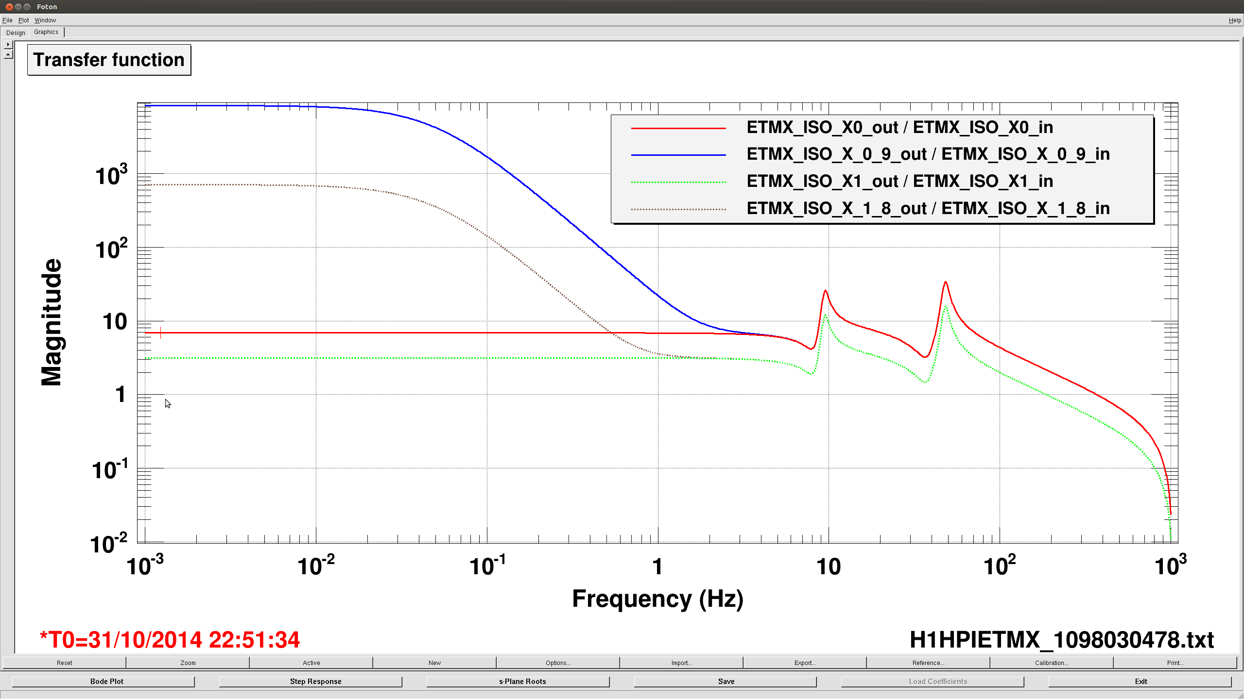
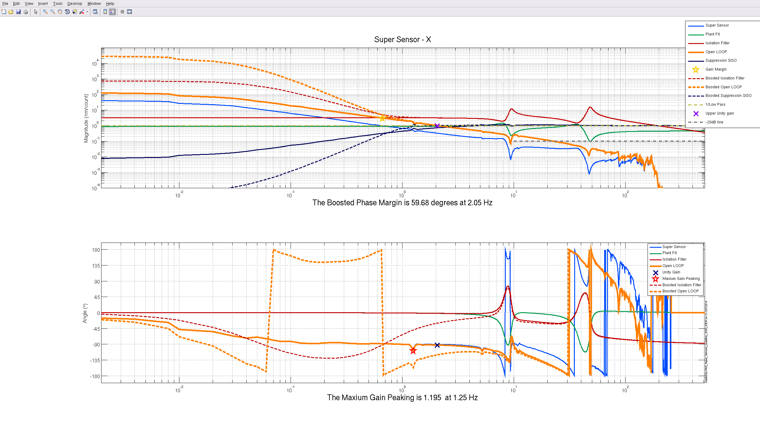
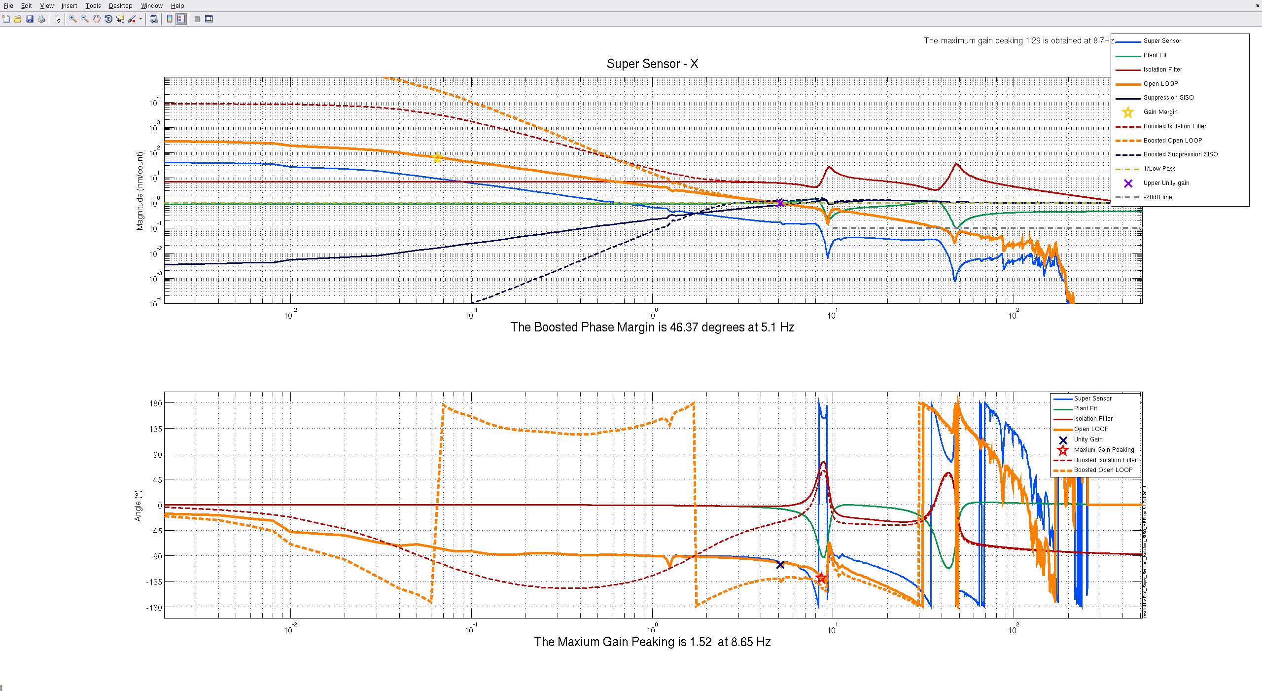
Here is another look at the controller with the amplitude scale zoomed out to see the lowest frequencies of the open loop.
J. Warner, K. Venkateswara
We repeated this measurement today and did not see the same results. Sensor correction was off. The attached pdf shows the before (old controller) and after (new low gain UGF controller) data. Very strange. We may have been fooled by different ground motion or perhaps by sensor correction. There is good coherence with ground till ~60 mHz in either controllerconfiguration.
Jim has reverted to the new low gain UGF controller as it should help with ringing of HEPI at 9 Hz.
