The current cdsutils installation (r361) has a new and improved NDS avg() function. The previous version was buggy, was calculating the standard deviation incorrectly, and had a clunky interface. This new version fixes those issues:
fixes to standard deviation calculation
The standard deviation was previously being calculated incorrectly and the returned values were wrong (off by some unknown but kind of large factor). The new version uses the python numpy.var() function to calculate the variance, from which the standard deviation is calculated. It has been verified to be correct.
channel IFO prefixes no longer need to be specified
Previously, the avg() function required full channel names, with IFO prefixes. This new version works like the ezca interface whereby the IFO prefix can be left off of the channel name. This makes things much cleaner, and allows scripts to be portable. E.g., instead of:
cdsutils.avg(2, IFO+':LSC-DARM_OUT')
just do:
cdsutils.avg(2, 'LSC-DARM_OUT')
new format for returned values
Probably the thing that's going to cause the most trouble is that the interface to the function has been fixed up. Previously, the function was returning a dictionary of channel:avg key pairs. This was very clunky to use.
The return value of the function now mirrors the input argument. So for instance, if a single channel is requested, a single avg value is returned. If a list of channels is requested, a list of average values is returned, in the same order as the input channel list. So calls like:
avg = cdsutils.avg(2, 'LSC-DARM_OUT').values()[0]
can now just be:
avg = cdsutils.avg(2, 'LSC-DARM_OUT')
If the stddev option is provided, the output will be an (avg, stddev) tuple, or if multiple channels is requested, a list of such tuples, e.g.:
avg, stddev = cdsutils.avg(2, 'LSC-DARM_OUT', True)
I have fixed all calls to cdsutil.avg() that I could find in the USERAPPS/release. I likely didn't catch everything, though, so be aware of the new interface and update your code appropriately.


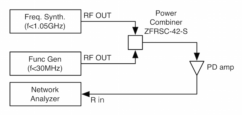
RF spectra from the 3-f BBPD have been posted to both LHO and LLO logs recently, so here is a comparison of those.
LLO data: log 15430 , photocurrent: 0.21 ma
LHO data: log 14807 , 27 mW -> inferred photocurrent: 3.0 ma (better would be a direct measurement of photocurrent)
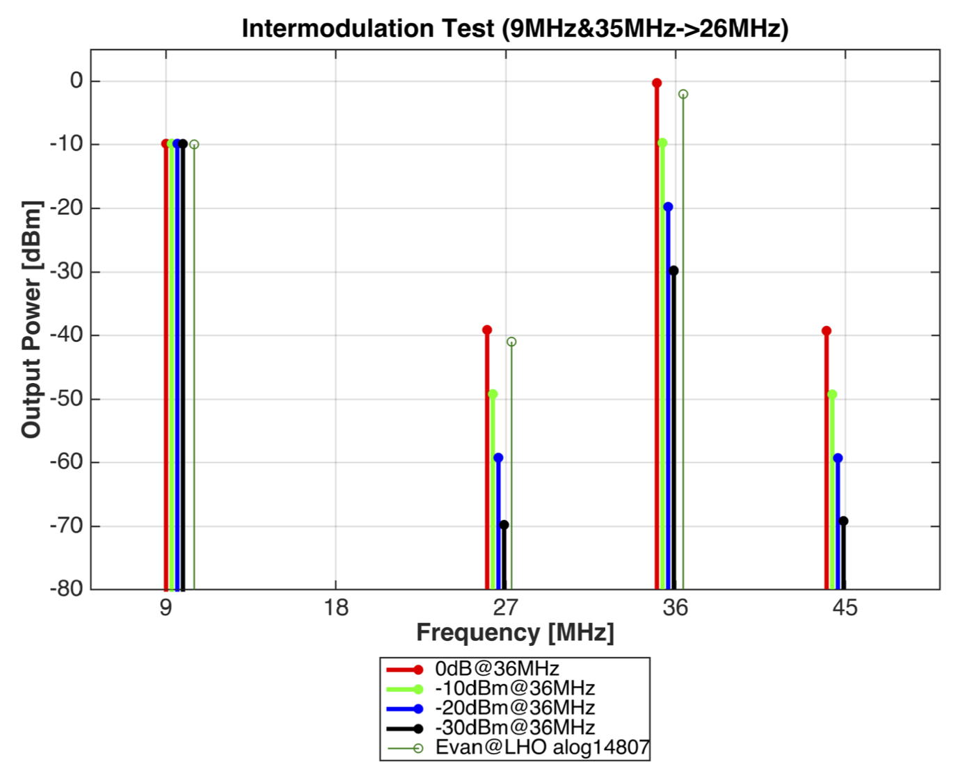
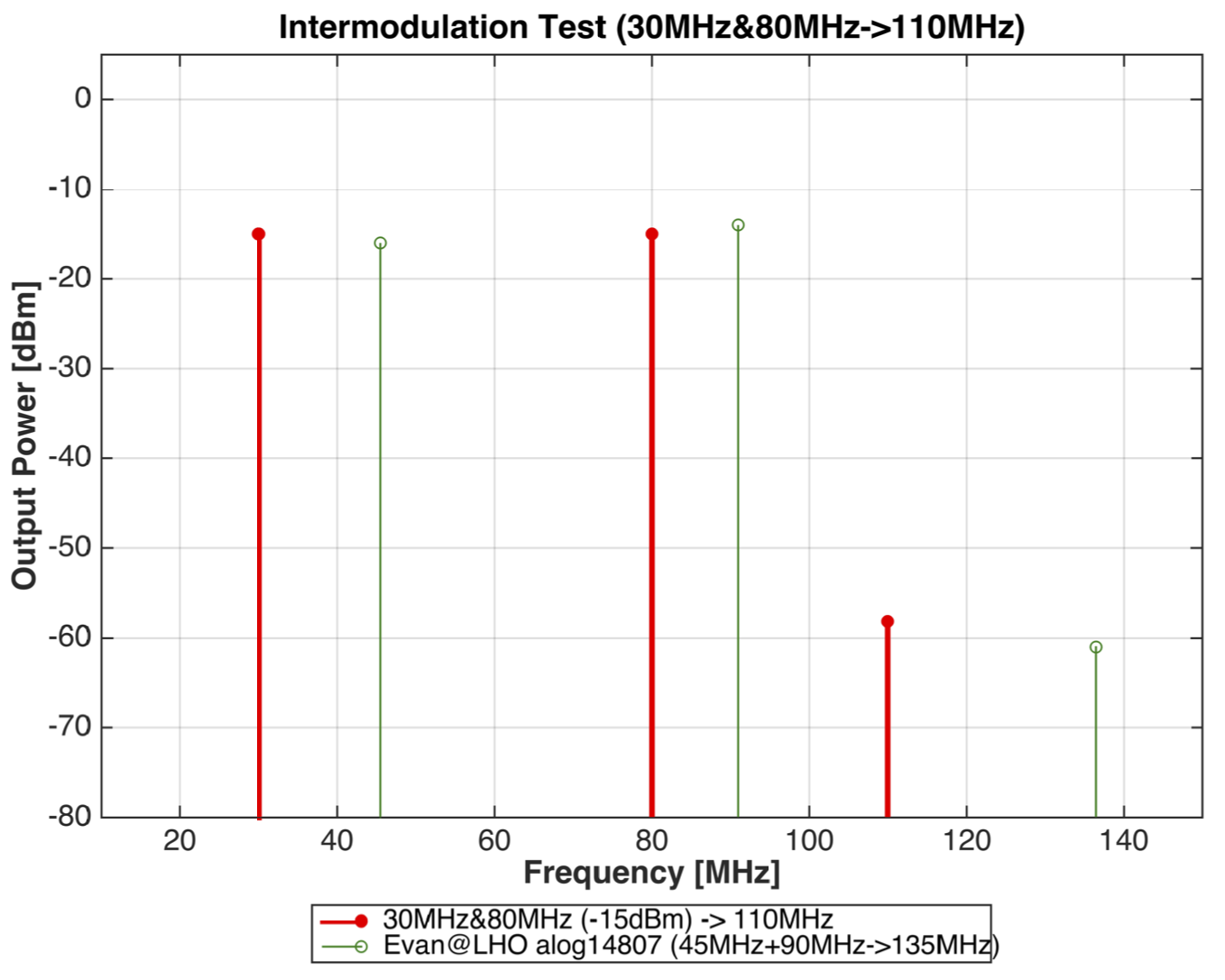
Comparison of 6 highest RF peaks:
Other than 9 MHz, the BBPD output RF components on H1 are all about 20 dB higher than the corresponding components for L1. This is about what is expected from the higher photocurrent used on H1 -- in fact we'd expect closer to 24 dB, if the inferred H1 photocurrent is right. The 9 MHz on H1 is another 10 dB higher (on top of the 20 dB), which is odd considering that the f1 modulation depth on H1 is smaller. This may indicate that on 3-f locking, there is more of an offset on PRCL (or MICH?) in H1 than L1, or maybe more residual motion.
In any case, L1 can hold a stable DRMI lock with the lower 3-f signal level, but H1 has not been able to so far. The LLO log entry also included demod error signal spectra for the DRMI. I'm hoping someone at LHO can post a comparison of that with the H1 situation.