08:00 resarted Alarm Handlers; CDS overview: noticed some conflicting counts on fw1 and some timing flags at the mid station; Vacuum: noticed IP-01 flashing red. Sent out emails to the corresponding folks for a check-out.
08:30 ISS loop coming in and out of saturation. Diffracted power all over the place. I bumped the refsignal up a click and the diff power stabilized. I tried a series of clicks following and got the diff power back up to ~7.6%
09:09 Betsy and Travis out to West bay to work on 3IFO Quad.
09:10 Andres out to W Bay
09:20 Peter F out to LVEA
09:55 J Bartlett, also Andres out of LVEA
10:25 Ryan reported a possible network outage lasting ~10 minutes maybe upstream of PM&L
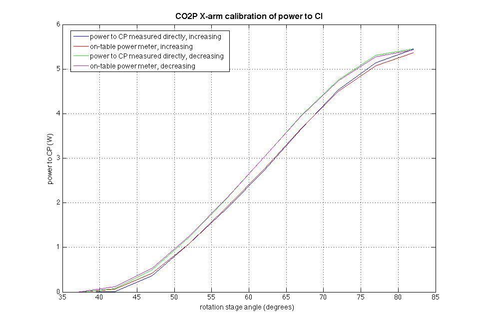
? Alastair putting power meter on TCS X arm table (WP 4925)
11:12 Robert working in beamtube between mid Y and end Y (shaking tests)
11:21 Dan to end X to look for equipment
11:56 Shivaraj to end X and end Y to mount magnetometers on tripods
12:38 ISS first loop went erratic again until ~
13:19 Karen at end Y
13:51 Karen out of end Y
14:30 Dan H out to HAM6
15:20 Rana brought to my attention folks entering VEA areas. Not everyone is reporting their desire to enter to the operator. Cleaning personell are calling after they've arrived at end stations.
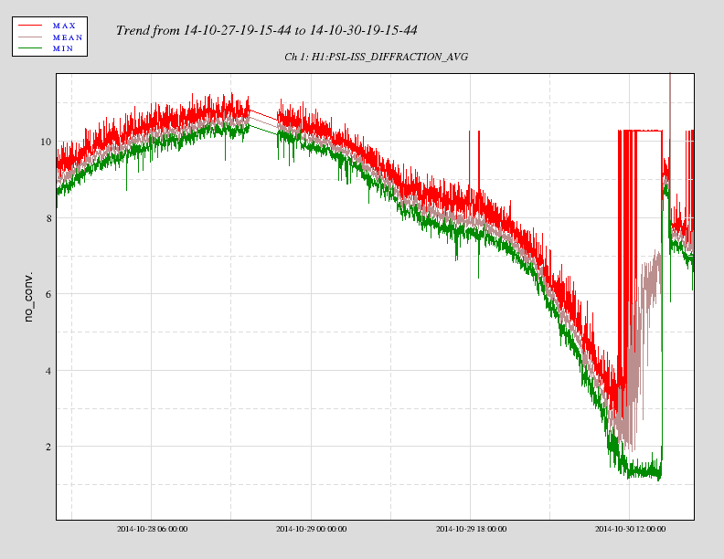


The ISS loop was sporadic all afternoon