J. Kissel, R. Adhikari, A. Staley, D. Sigg, D. Barker, J. Batch, H. Radkins
Something non-nonsensical happened to H1 SUS MC2 this afternoon, it's fixed now. Too many things had gone on, lots of red herrings causing more random button clicking, and not enough people were fully aware of tall components involved to make sense of it while it was going on. I've tried my best to find out what happened by trending channel after channel -- I quote the time-line of everything I could find, but there's no smoking gun. Chalk this up to a one-off badness. IMHO, there's no point in chasing further because too many thing things happened at once, too quickly, without a clear diagnosis or clear plan to fix it.
As an aside, we need to standardize our HSTS damping loops. Its my fault for not having a complete model and organized damping loop design for these suspensions. In its absence, folks have found various configurations that make them happy that day, and now, because it "works", no one wants to change anything nor knows what the "right" status is.
All times UTC on 2014-Oct-23 (but 14:08 UTC is 7:08a PDT 2014-Oct-23)
14:08 IMC Flailing for lock, rapidly bouncing between Guardian state INIT and LOCKED.
|
| 16:20 h1fw1 dies, dropping all trend data for a few minutes. This is the default nds server for data viewer, so it looks like this is the cause of the problem, [first red herring] but looking at h1fw0 data shows not drop out.
V 16:23 H1 SUS MC2 starts to veer off in Yaw by hundreds of micro-radians
16:24
16:26 H1 SUS MC2 LF and RT output signals (the top-stage, M1 OSEMs which control longitudinal and yaw) gradually start to increase their signal
16:35 Hugh begins to take down *HAM2* (Note -- NOT HAM3, the chamber in which H1 SUS MC2 lives [second red herring]). Hugh later confirms that HAM3 ISI and HPI remain rock solid throughout.
|
| Problems with correcting ISI matrix elements means HAM2 ISI fights to come up and down (see LHO aLOG 14594)
| 16:40 UTC H1SUSMC2 top mass M1 outputs begin to constantly saturate
V
19:07 HAM2 ISI recovers from problems
20:18 IMC guardian atempts to resume locking
21:03 Alexa find that H1 SUS MC2 is off in the weeds in Yaw by looking only at the bottom stage OSEMs, moves the alignment sliders hundreds of urads to push the top stage M1 to compensate for what she sees
21:07 IMC WFS automatically begin trying to compensate for Alexa by requesting hundered the M1 LOCK Y output hundreds of urads in the opposite direction
21:08 IMC WFS have compensated for Alexa, and restored MC2 to early morning location
21:31 Alexa turns OFF the IMC by seting the LSC-MC_GAIN to zero, instead of asking the guardian to stop trying to lock. IMC LSC control is NO LONGER GOING TO THE SUSPENSION [third red herring]
21:34:27 Rana turns on FM10 (Ellip50) of the DAMP L bank, changing the SWSTAT from 5140 (only FM3 and FM5) to 5652. The damping loops have been at SWSTAT 5140 for 120 days (separate trend), implying the "correct" state*** for MC2 is with FM2 OFF.
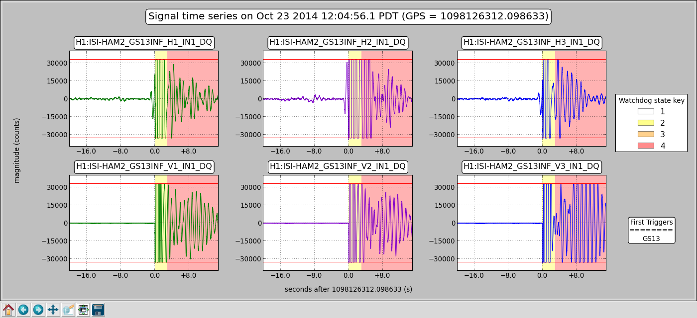
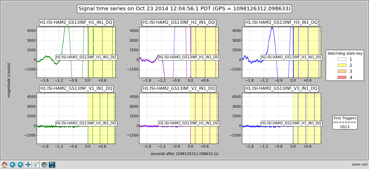
21:34:37 H1 SUS MC2 User Watchdog Trips, killing all output to M1 TOP stage
21:34:40 H1 SUS MC2 IOP Watchdog Trips, killing all output to entire suspension
21:35 H1 SUS MC2 longitudinal damping loops begin oscillating, because damping has been turned off and suspension is shaking -- BUT NO OUTPUT IS GOING OUT, so there's nothing wrong with the damping loops [fourth red herring].
21:35:56 USER watchdog is untripped, IOP Watchdog is locked up (won't reset), unclear why.
21:39 Rana tries different configurations of the L filter banks, trying to find one that's stable, settles back on FM3, FM5, and FM10.
21:39:42 Alexa successfully untrips IOP watchdog. Unclear why.
21:46 Alexa turns the MC_GAIN back to 1.0, allowing IMC control to resume requesting the IMC to be locked, though some how the guardian status claims the IMC has been in the locked state since 21:07, with only short dropouts at 21:13, and 21:30. I don't know what the IMC guardian watches, but it doesn't seem to be accurate.
21:47 IMC locks stably. Problems resolved.
Also, the h1nds0 died thrice after I'd switch to using it to avoid the h1fw1 data drop out (only reported once in LHO aLOG 14598).
DetChar is welcome to take a stab at it, but there's just about zero chance of reconstructing this perfect storm tornado.
*** This was NOT the problem, but I summarize the complete dis-array of the HSTS L damping loops:
MC1 FM3, FM5, G = -3
MC2 FM3, FM5, FM10, G = -3
MC3 FM3, FM5, G = -3
PRM FM3, FM5, G = -1.55
PR2 FM3, FM5, FM10, G = -1.55
SR2 FM3, FM5 G = -1.55
SRM FM3, FM5 G = -0.55
I would post dataviewer trends, but the time axes tick labels are spaced so far apart for an 8 hour trend that it's useless. I can zoom in live, and use my cursor to identify exact times (which is how I composed the above timeline), but upon zooming in, the time axis tick labels go from far to sparse to unreadably over-dense.
#houseofcards