Hugo & Hugh
With new ISI TFs from Sept 16 when the ISI was Under Vacuum with the HEPI Position Loops closed, I made new Level 3 control scripts for HAM2. I took the ISI down with Guardian pausing the manager and putting the ISI in READY.
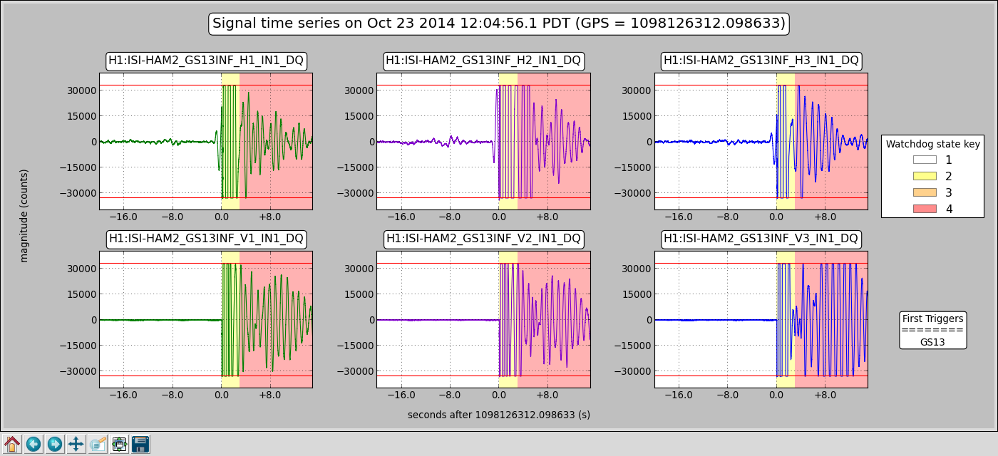
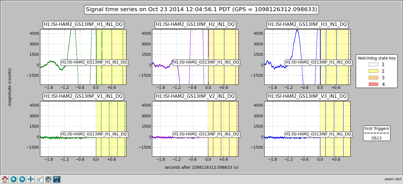
In this state, the local 2 cartesian (& back) matrices were corrected--the X Y RX & RY signs were incorrect-- using the Populate_Matrices_HAM_ISI.m function. As expected, the cartesian sign of these dofs switched and the Target Position was correspondingly changed (by hand.) I then loaded the new filter file. Everything as expected so far. When the ISI Guardian was set back to High Isolate, it performed as expected until it was changing the horizontal dof gains from 0.01 to 1.0. At this point it trips in a fraction of a second on the GS13. In subsequent attempts it almost always repeats this behaviour although sometimes the trip was the actuator rather than the GS13, see the attached for example and zoom in.
OK so I screwed up the controllers. We tried level 2 controllers. Wait Guardian isn't set up to do level 2 so I try the old ISI Command scripts: yes it works on level 2 & level 1...
So Okay, I must have screwed up the controllers. I reverted back to the achive file that was made Oct2 10:16: still Guardian trips the level3 attempt at the same spot... revert back to Oct2 10:13 (what's up with that?.) Same result.
We try some manual turn on, that is 1 dof at a time, hey we can isolated this way. Then we take it down again and try with Guardian, no, it still turns on the Vertical Dofs fine but trips when switching the Horizontal dofs from0.01 to 1.0 gain.
Then! Then we try level 3 with the old ISI command scripts--it works! We turn Guardian back on, take the ISI down to ready and then attempt to get back to Isolation, nope, sorry, still trips. Back up to level 3 Isolation with the old ISI command scripts. This is where it sits...Strange.
Strange in that the ISI command script turns RX & RY dofs on first while Guardian does Z RX & RY first. Then when the command scripts have to do Z X Y & RZ, Guardian only has to do X Y & RZ. Plus, guardian does everything sequentially as in it waits for boosts to be on before he next step whereas the old command scripts are often doing more things at once such as engaging the boost while starting the Alignment bias servoing.
So we have to conclude that something must be up with Guardian although it seems unlikely. I restarted all Guardians 16 October and all went back to high isolate with no problem.
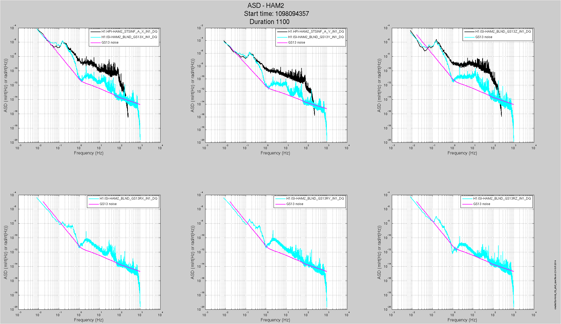
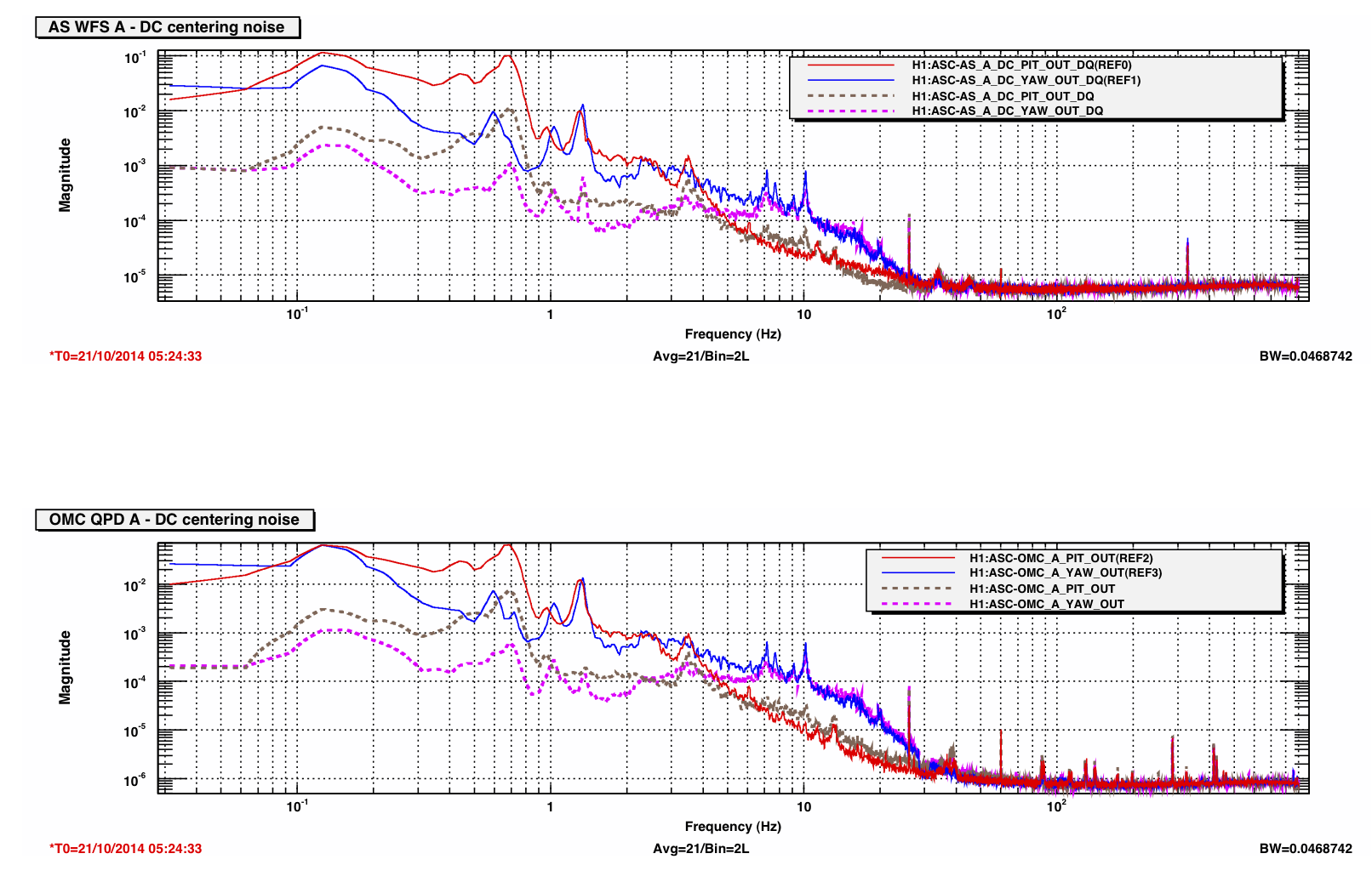
We have a before these changes performance plot. We'll take another look after things settle down and compare.
Summary
Matrices and Controllers reverted but ISI will not Isolate with Guardian. It does Isolate using the old ISI Command Scripts.
re "I restarted all Guardians 16 October and all went back to high isolate with no problem."
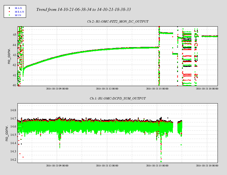
I actually didn't bring the isolation down. The Guardian was restarted without impacting the platform, so it could be that there is a long standing issue with Guardian. Based on the Watchdog trip indicator, Oct 2 was the last time the HAM2 ISI tripped but of course that doesn't mean someone might have run the ISI down with the Guardian. There are some ODC BIt changes around 16 Oct...
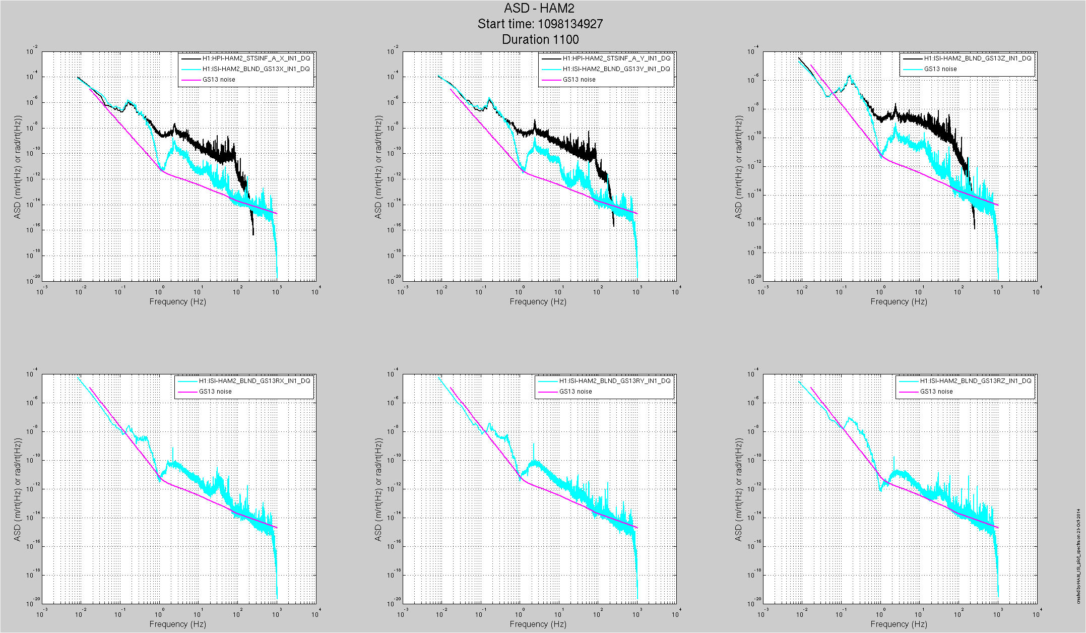
It may not be a fair comparison: The first attached plot is the ground motion and HAM2 GS13 spectra at 3 this morning with 100mhz blends on the X Y Z dofs, 01_28 blends elsewhere. The second plot is from 1430pdt where we have 01_28 filters on all dofs. Of course the input ground motion is different,there is more motion on the ISI X Y Z dofs in the 1 to 10hz band. The other dofs are pretty similar. We'll put these blends back and check when the commissioners can deal with the change.