J. Warner, K. Venkateswara
Using Jeff K.'s model modifications, we were able to incorporate BRS tilt-subtraction to the GND_STS which was then output to STS_C channel (which was empty previously). This was then used for sensor correction by changing the cartesian conversion matrix. The tilt subtraction filter uses a simple acceleration to velocity converter, a gain matching and a high-pass filter.
Rich M. wrote for us a neat IIR filter to try out for the sensor correction filter bank. After the first attempt doubled the ground signal, we used this with a gain of -1.0 which worked well :)
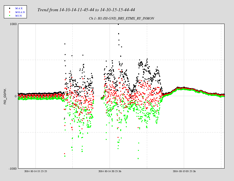
We wanted to try out this sensor correction yesterday, but there was a lot of activity at ETMX which was disturbing the BRS as shown in the attached .png file. The good news is that immediately after the activity ceased, the BRS output settled down so the damper continues to work as expected.
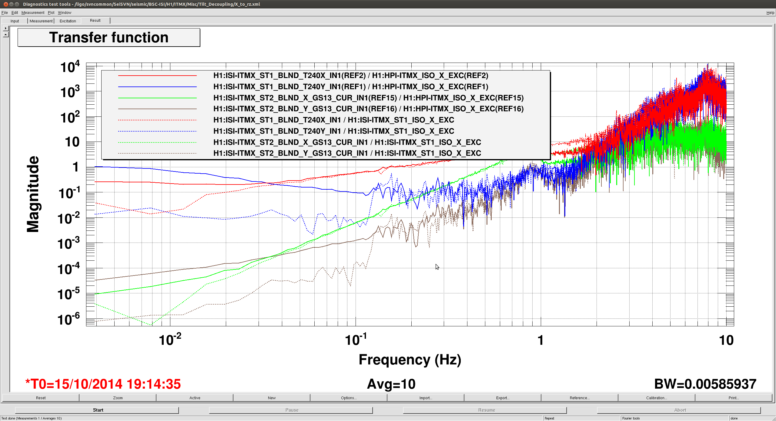
This morning we had some time to try it out before EX activity resumed. The file NoSensCorr45mHzblnd.pdf shows the current ISI stage 1 performance with the 45 mHz blend filter. As I've mentioned before, notice the nice coherence with the GND_STS_X and ST1 T240_X between 0.1 to 0.6 Hz. The Y-axis is in counts (velocity).
For the uninitiated, sensor correction adds the ground sensor signal to the position sensor, thus it is effective only below the onboard inertial sensor blend frequency. In this case, since we wanted to do sensor correction in the 0.1-0.5 Hz band, we shifted the inertial sensor blend to 250 mHz. The two files NoSensCorr250mHzblnd.pdf and SensCorrOn250mHzblnd.pdf shows the Stage 1 motion without and with sensor correction respectively. Even with sensor correction on, this configuration seems to be a factor 2-5 worse in the 0.1 to 0.5 Hz band, but it is very interesting that the coherence with GND_STS_X is much smaller. And there is significant coherence with ST1_T240_Z at the microseismic peak. This might be related to what I mentioned before in 14426.
But to our surprise we were injecting noise below 0.1 Hz. I then rechecked our tilt-subtraction filter and it turns out we had one filter gain wrong. I've corrected it and I verified that the tilt-subtracted super-sensor was indeed smaller than the ordinary ground sensor. Unfortunately, EX activity resumed just then and we couldn't verify that the sensor correction was lowering the noise below 0.1 Hz. The ISIs were restored to the 45 mHz blends for commissioning activity.
Summary: Our first attempt at trying sensor correction with the ground 'super-sensor' was not terrible! :) We will do a more refined attempt tomorrow. We will also try doing sensor correction using HEPI which may give slightly different results.