[This work was done last week, but I forgot to submit this log.]
I added NOMINAL state definitions for all SEI systems, including HPI, ISI stages, and HAM and BSC chamber managers. All SEI guardian nodes were restarted to affect these changes.
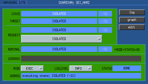 NOMINAL state for HAM managers is "ISOLATED".
 NOMINAL state for BSC managers is "FULLY_ISOLATED" (HPI and both ISIs isolated).
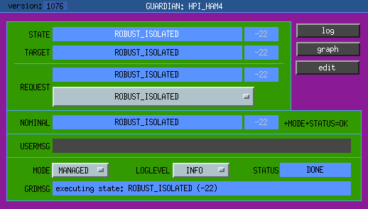 NOMINAL state for HPI is "ROBUST_ISOLATED", for both HAMs and BSCs.
 NOMINAL state for ISI stages is "HIGH_ISOLATED".
Other than HAM 5 and 6, which are still being commissioned, everything except BS is set to be in the NOMINAL state, and is in the NOMINAL state.
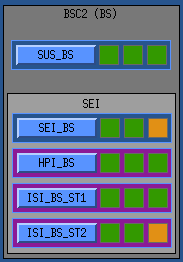
We are currently operating the BS ISI with only stage 1 isolated, and stage2 left damped, corresponding to "ISOLATED_DAMPED" in the BS chamber manager (MICH locking has a tendency to trip the ISI stage 2 if isolated). However, I decided to leave the NOMINAL settings to the default for ISI_BS_ST2 and SEI_BS, so that we're reminded to address this issue down the line. Here's a crop from the GUARD_OVERVIEW, showing that the SEI_BS and ISI_BS_ST2 are not in their nominal states, as indicated by the far left OK indicators being orange:
We still need to add numeric indices for all the SEI states. This will require a bit more work for SEI since the HPI and ISI states are generated based on the particular configuration.