The story made brief
In a previous alog entry I pointed out that most of the intensity nosie we see in transmission of the IMC is due to input beam jitter converted to RIN due to an IMC misalignment. Today, to prove this, I improved the IMC alignment in three steps:
-
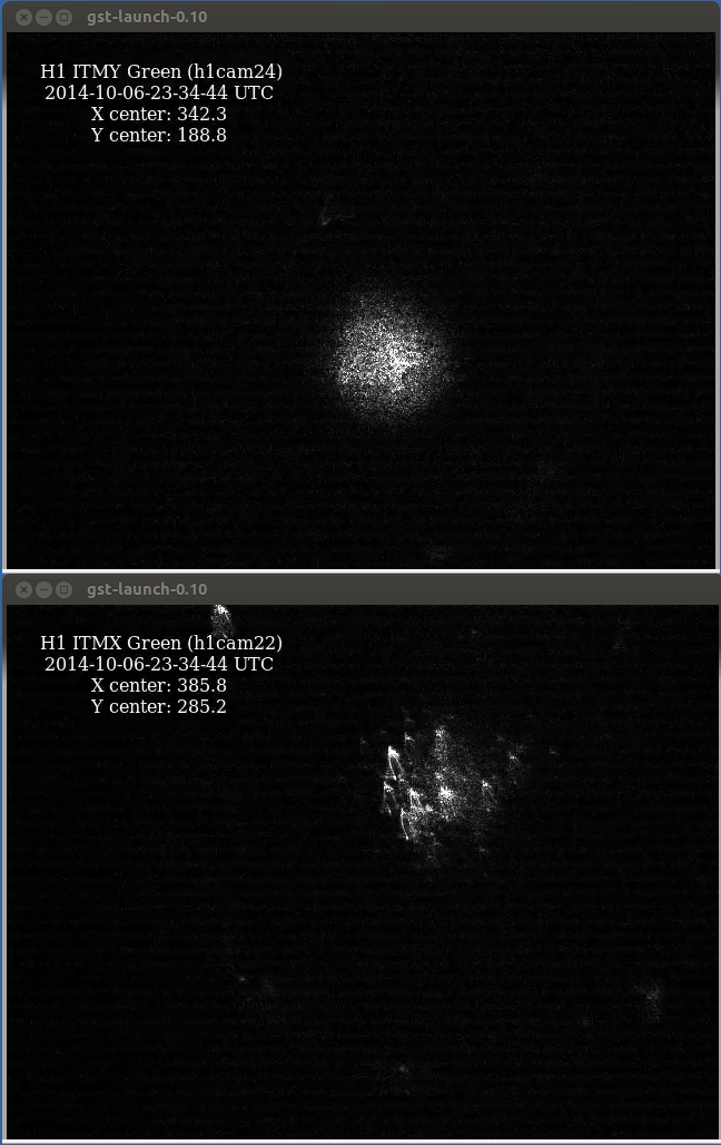
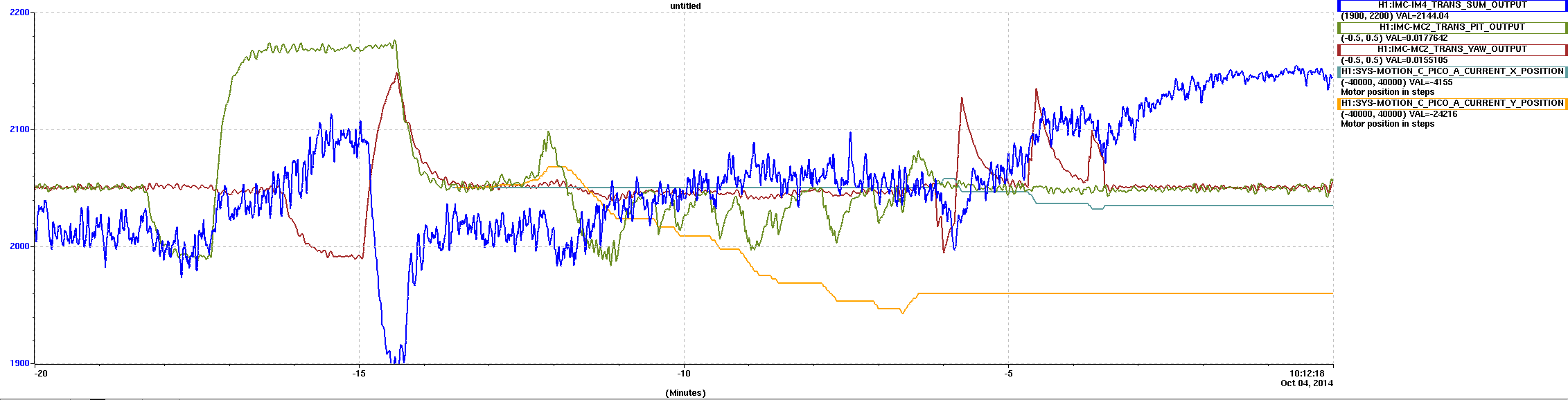
First of all, I tuned the DC alignment by moving the beam on MC2_TRANS QPS. This improved significantly the power transmitted by the IMC, as visible in the first plot. The IMC transmission increased by 7%, from 2020 counts to 2160 counts (in IM4_TRANS_SUM). This re-alignment also reduced the intensity noise at the output of the IMC.
-
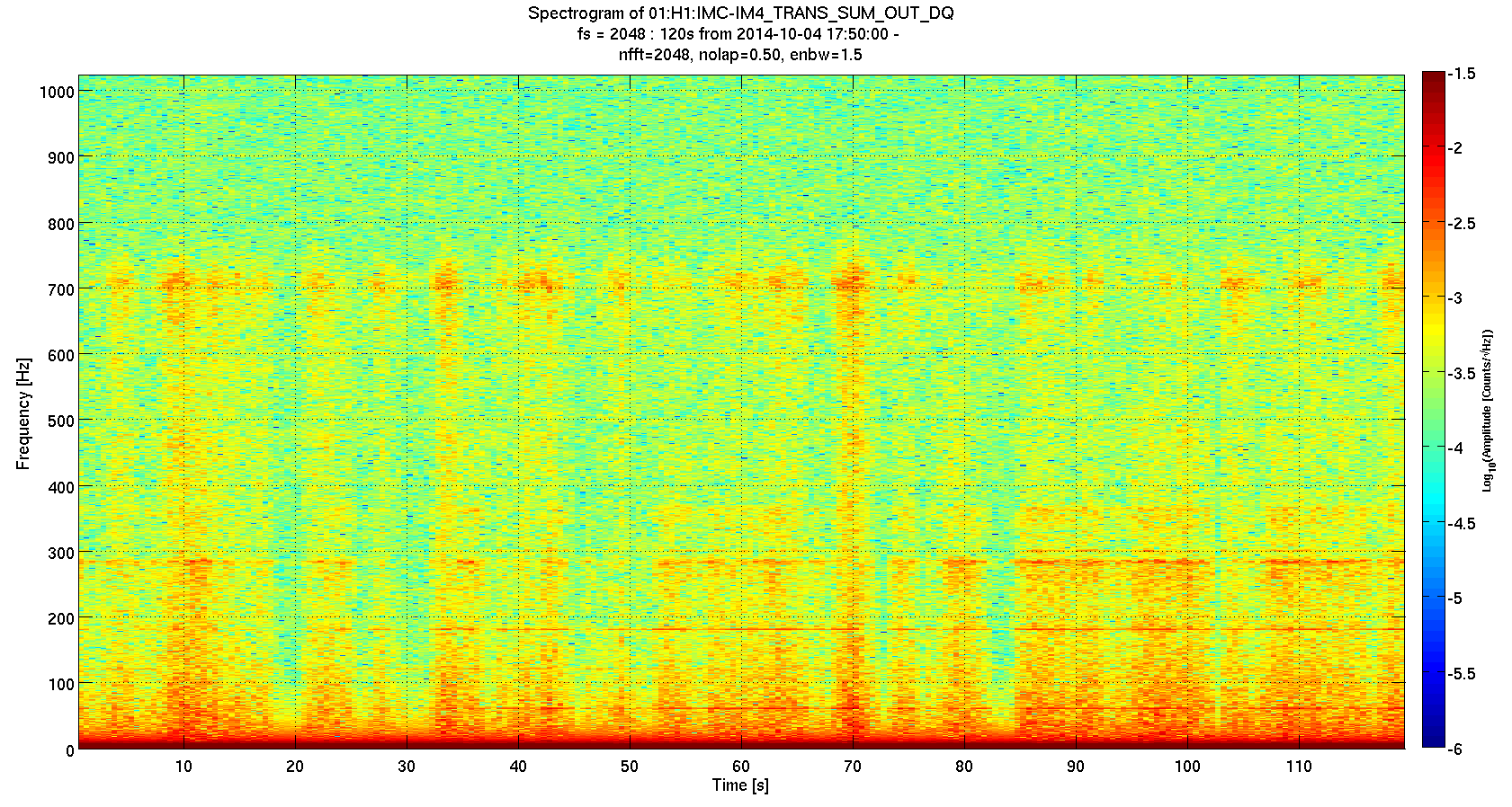
However, the RIN was still highly non stationary, as shown in the spectrogram attached as second plot. I used some non-stationary analysis technique (described later) to track down the RIN modulation to the residual motion of IMC_DOF_1 yaw. Measuring the loop, I found that the UGF was likely few mHz, so I increased the gain by a factor 20 (gain from -1 to -20). I applied the same cure to DOF_1_P and DOF_2_*. This reduced a lot the error signal residual RMS, and also the RIN.
-
I added two offsets to DOF_1_P and DOF_1_Y, both -20 counts. This reduced even further the RIN at the IMC transmission.
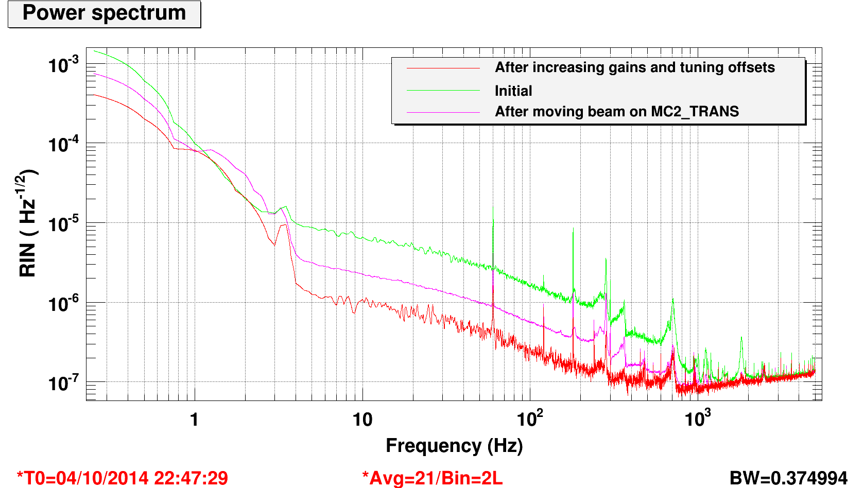
The third attached plot shows the improvement in RIN in transmission of the IMC. Now it is at a level of 1e-6 at 10 Hz and 2e-7 at 100 Hz. It's almost a factor 10 better everywhere.
It's interesting to note that the RIN is still non stationary, so we should improve further the IMC alignment accuracy. I could not increase more the gains of DOF1 and DOF2, since I got a 1 Hz instability (as expected from the open loop transfer function). However, my intuition is that the IMC mirrors are pretty much not moving, and instead the input beam pointing is moving a lot. So we should servo the input beam to the IMC cavity axis with some Hz of bandwidth. This is what we did at Livingston, where the input beam motion was limited by air currents in the PSL room. I believe a similar approach should be used here. This is much better than high bandwitdh loops on the mirrors, since they should be our best reference.
Some details
Non Stationarity analysis
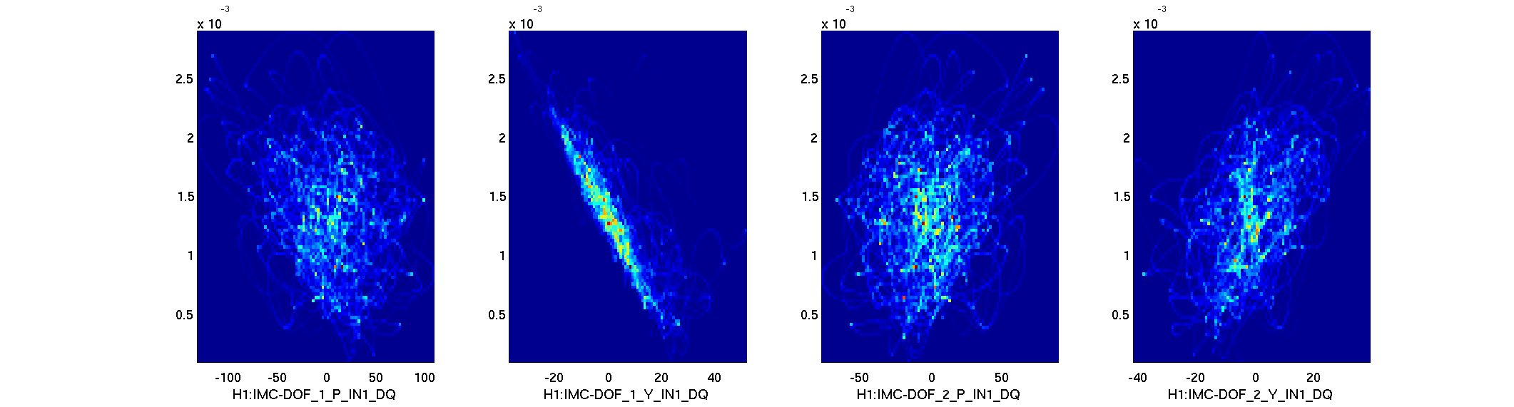
To study the dependency of RIN on IMC angular fluctuation I used a code developed for a similar task at Livingston. See more details here. In brief, i compute the band-limited RMS of the IM4_TRANS_SUM signal between 50 and 10 Hz, and correlate this with the low frequency content of the IMC alignment error signals. The scatter plot in the 4th attachment shows the correlation between each IMC angular DOF and the BLRMS. There is a clear correlation with DOF1_Y. From the scatter plot we can also see that there is an offset on the error signal.
A more quantitative analysis can be obtained by fitting the BLRMS time series with a linear combination of a constant, the error signals and their squared values. The procedure I used is a slightly modified version of a LSQ fit, and it gives me a ranking of the signals as a function of their importance in improving the fit. The code is attached to this entry. Basically, the first step is to find which one of the channels (constant, error signals or their squares) can be best fit to the BLRMS. finding the minimum residual squared error. Typically a constant is the first winner. Then the procedure is repeated with the residual, looking for the single bets channel to furher reduce the rfit error. At each step I search for the channel that reduces the error the most. The procedure is repeated iteratively.
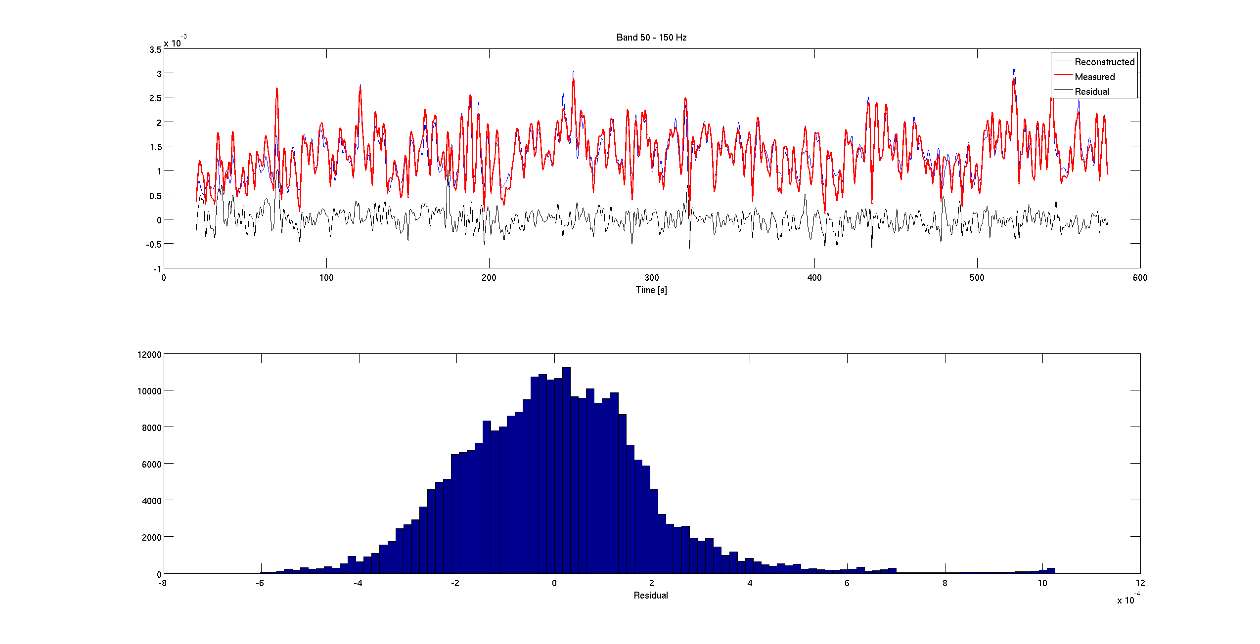
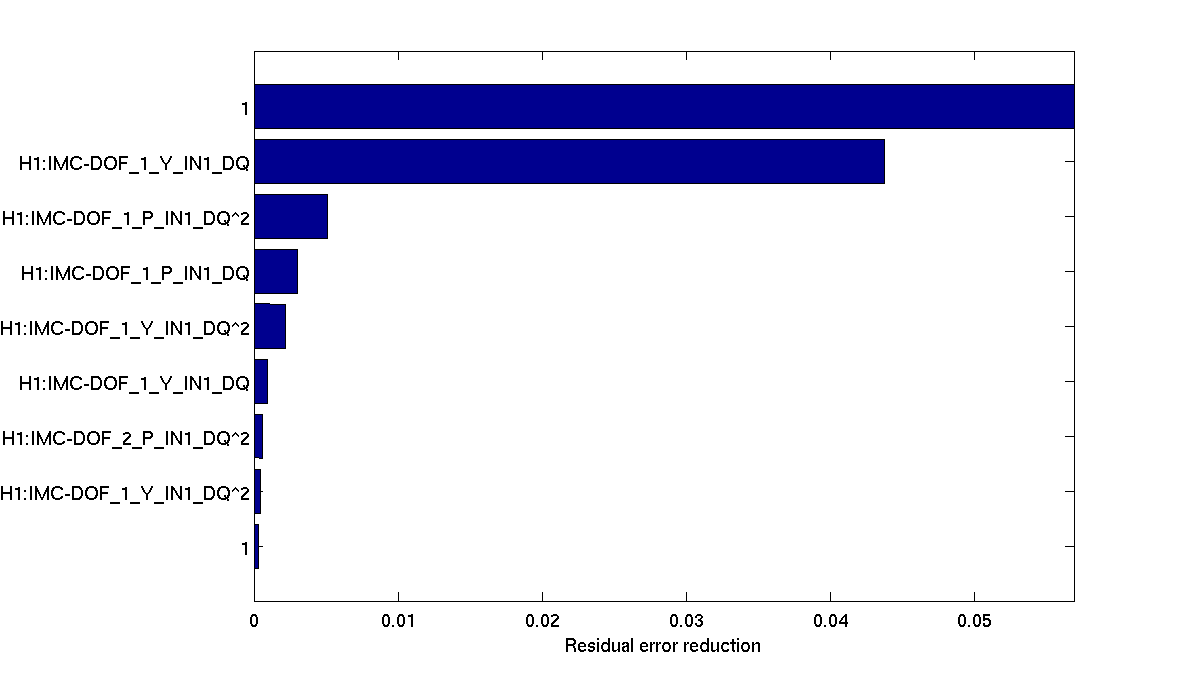
The 5th plot shows the result of the fit before any improvement on the IMC alignment. Most of the noise fluctuations could be explained by angular motions. The 6th plot shows the ranking of the channels (the bigger the bar, the most important the channel is), confirming that DOF_1_Y is our best candidate.
DOF_1 bandwidth
The 7th plot shows the measured open loop transfer function of IMC DOF 1 Y before and after my gain increase. The loop had a bandwidth of probably 3 mHz with the original gain of -1. The plot shows the OLTF with a gain of -100, giving a badwidth of 300 mHz. I did not measure the other DOF1 and DOF2 loops, but I could increase their gain in a similar fashion.
After some tweaking, I reduced the gains to -20, since the error signals were showing a large 1 Hz instability, which is consistent with the measure OLTF. However, we are clearly still limited by the residual motion of the beam with respect to the cavity axis.
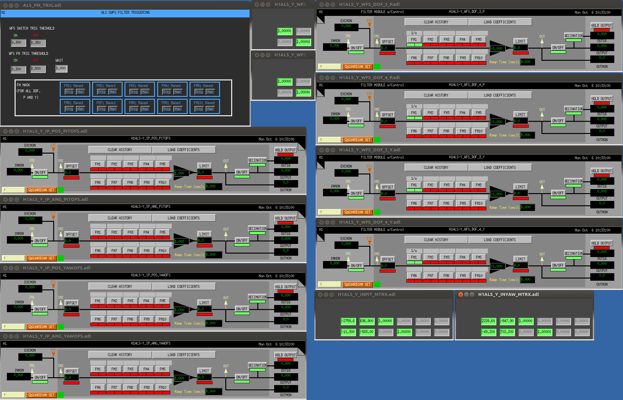
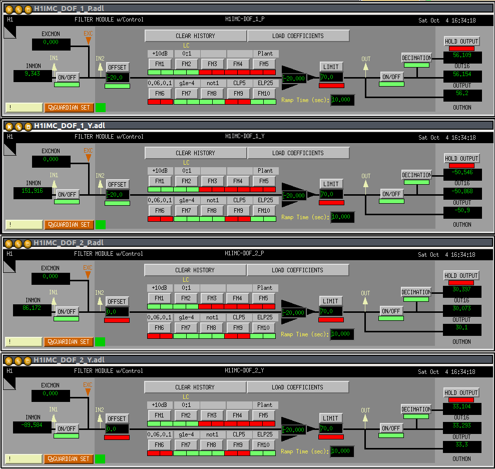
I'm leaving this configuration running, as shown in the attached screenshot. In case there is any problem, revert back to the original configuration by reducing the gains to -1 and removing the two offsets. No other modification will be needed.
WFS offsets
Since I don't like much the idea of running WFS loops with offstes, I tried to zero them by moving the beam on the WFS using the picomotors, but I couldn't get any effect at all, no matter how big step I was moving.


Here is a lockloss science. Not clear what exactly was going on.
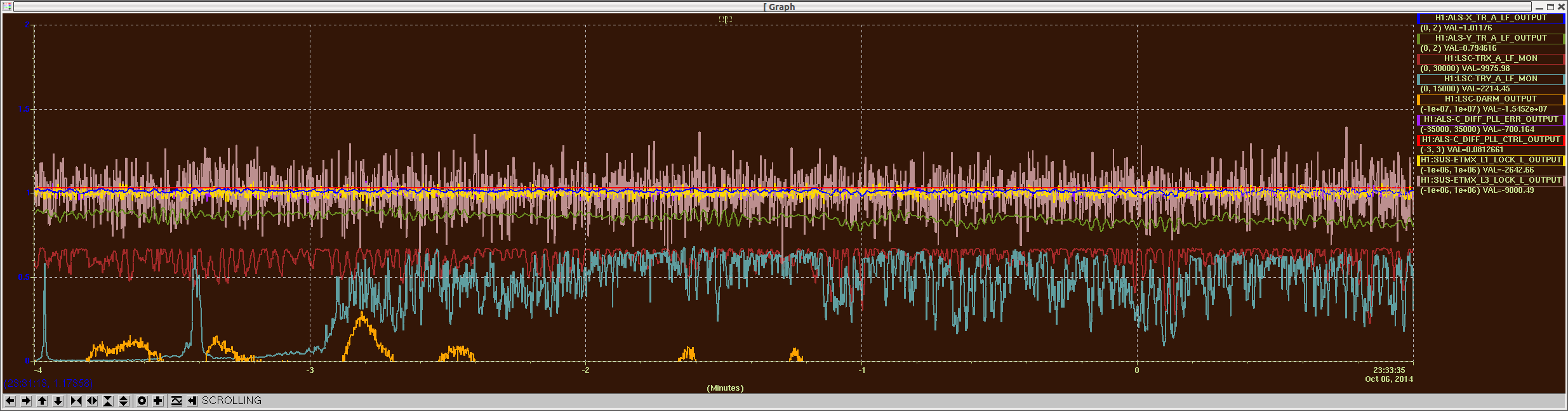
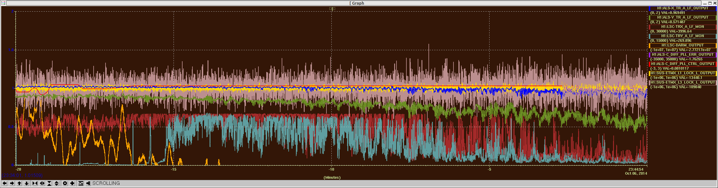
I looked at three different lock loss events from yesterday. All of them were associated with very large saturation in the M2 stage of SRM which seemed to trigger instability in SRCL and destroy all the LSC loops eventually within a 2 sec or so.
The attached plot is the one from Oct-07-2014 09:24:22 UTC. In this example, PRCL and MICH had been already controlled by the 3f signals (i.e. RF27_I and RF135_Q respectively). In the middle of the plot, the SRCL 3f signal was ramped up (though it actually ramps down because of the control sign. The 1f signal was ramping down at the same time which is not shown in the plot.) Apparently the SRM M2 stage saturated quite hard. Following the M2 stage, the SRM M3 stage hit the DAC range as well. The BS and PRM M2 stages did not saturate until the loops became completely broken. An oscillatory behavior was seen in all three length signals and it was roughly at 13 Hz. Hmmm...