jenne.driggers@LIGO.ORG - posted 00:26, Thursday 02 October 2014 - last comment - 01:01, Thursday 02 October 2014(14268)
DRMI work tonight
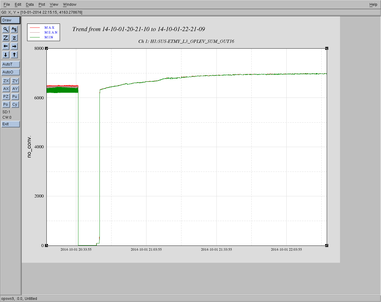
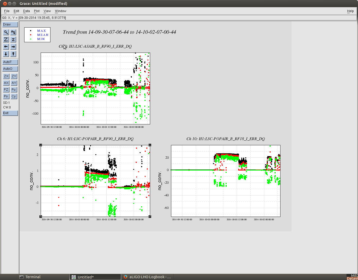
Alexa, Kiwamu, Sheila, Jenne

This is sheila, accidentally logged in as Jenne

We made some attempts tonight to transition DRMI to 3F.  We see that we don't have much signal in the 3F detectors at 1 Watt, so we have been transitioning manually to 10 Watts after lock is acquired.  We have transitioned PRCL successfully several times, with a gain of 1.5 in the input matrix, this is handled by guardian.  We have tried srcl, and used 60% of the 3F with 40% of the 1F.  Our next steps are to get some asc loops running, so that we don't spend as much time manually aligning DRMI, and also to try transitioning mich after prcl.

The rotation stage has a lot of hysteresis, we will ultimately want some sort of servo to make sure that the input power is what we requested.

Kiwamu has measured the modulation depth: yesterday AS RF 90 was 33 counts, today (with the 19 dB RF amplifier and 6dB attenuator installed) it is 270.  This was consistent with the OMC scan which were the height of the 45 MHz sideband with DRMI locked was 0.3, today it was 3.  (These both mean that the modulation depth increased by roughly a factor of 3).  The gains in the guardian have been adjusted to take this into account.

The good news is that we have locked DRMI many times tonight, it normally locks within a few minutes.  Also, the attached screen shot shows that DRMI was locked on 1F for about 10 hours last night.
Images attached to this report
Comments related to this report
A fortuitus lock as we were about to leave let us transition to 3F (at 1 watt input power) , which was stable for about 15 minutes before it dropped (we were aligning) at 7:57 UTC october 2nd. For srcl we used -2 in refl 135 I, for prcl we used 1.5 in refl 27 I, and for mich we used -0.43 in refl 135 Q. ( we transitioned prcl, then mich, then srcl). the rms at the coil output for srm m2 is 3*10^4 counts.