For those interested in looking closer at QUAD model parameters, attached are plots comparing all of the QUAD Main Chains when suspended with wires and also when suspended with fibers. Note, if QUAD data is missing for one of these configurations it's because there was no clean data available. Between the 2 plotted configurations, all 12 (H1, L1, and 3IFO) QUADs are represented. Note, I tried to chose data sets that had the same or similar environmental conditions, but it was difficult due to the fact that some QUADs were reworked on test stands and some were reworked in chamber. In all cases they were mounted on Solid Stack Test Stands or Locked ISIs and in-air.
Data is committed to the svn and can be found at:
/ligo/svncommon/SusSVN/sus/trunk/QUAD/Common/Data/
There does not seem to be a pattern in the data of the 2nd pitch mode peak which are clustered by a specific type of suspension (ETM vs ITM, or wire segment hang vs wire loop hang).

And now with some cursors and in a second format for Brett.

As suggested, I looked at the stiffnesses of the Top Mass blades to see if there is a correlation with the second pitch mode frequency shifts. I don't see it. In order of the peaks on the P to P plot, starting with the lowest frequency to the highest the blade sets used in each QUAD are:
H1ETMx - SET 9 (~1.28Hz)
L1ETMy - SET 13
L1 ETMx - ?
L1ITMx - SET 14/15
L1ITMy - SET 12
Q8 ETM - SET 8
Q9 ETM - SET 2
Q6 ITM - SET 10 (~1.531 Hz)
The blade sets go in order of stiffness from highest to lowest, so SET 2 is stiffer than SET 15. SET 14/15 is a mixed SET with blades still of adjascent stiffness.
I took the two wireloop quads that have the highest and lowest 2nd pitch mode frequencies and made a fit to them. These measurements and their respective made-to-fit models are shown in the attached plot. QUAD06 (H1 QUADTST) is the highest, X1 ETMX is the lowest.
I previously did a fit for QUAD06, see log 14235. The fit for X1 ETMX was made simply by taking the QUAD06 fit and subtracting 3 mm from dn, which works quite well.
Since the outliers are 3 mm apart on dn, the other quads seem to have an even spread between those, and no correlation with spring stffness is evident, then a possible explanation is that our tolerance on positioning the top mass blade tip height is +-1.5 mm.
Attached is a prediction of what +-1.5 mm on dn would look like for the fiber quads.
The black is a model of H1ETMY (which has been the default fiber model for some time) where dn=1.78 mm; blue is the same model but with dn=0 mm; red is again the same model but with dn = 3 mm. Some data is included as well. The H1ETMY measurement is in orange, which matches well because of the previous fitting of H1ETMY. In purple is H1ETMX. I think H1ETMX corresponds to the wireloop quad X1ETMX, which was the low outlier on dn for the wireloop configuration. In that configuration a dn of 0 mm worked quite well to the fit model to the data. Here the same 0 mm dn makes almost as good of a fit. There is not data matching the dn=3mm. +3 mm was found to work well for the high dn outlier wireloop QUAD06, which is not yet a fiber quad.
So it seems that for the existing fiber quads, +-1 mm on dn explains the spread well. However, the most recent 3rd IFO quads, still with wireloops, are the stiffest yet in pitch, so they would be expected to bring this to +-1.5 mm and line up with the dn=3mm red curve.
Posting some notes from recent email converstions looking into the large apparent shifts in dn (top mass blade tip height) and d2 in the all metal build (PUM wire loop prism).
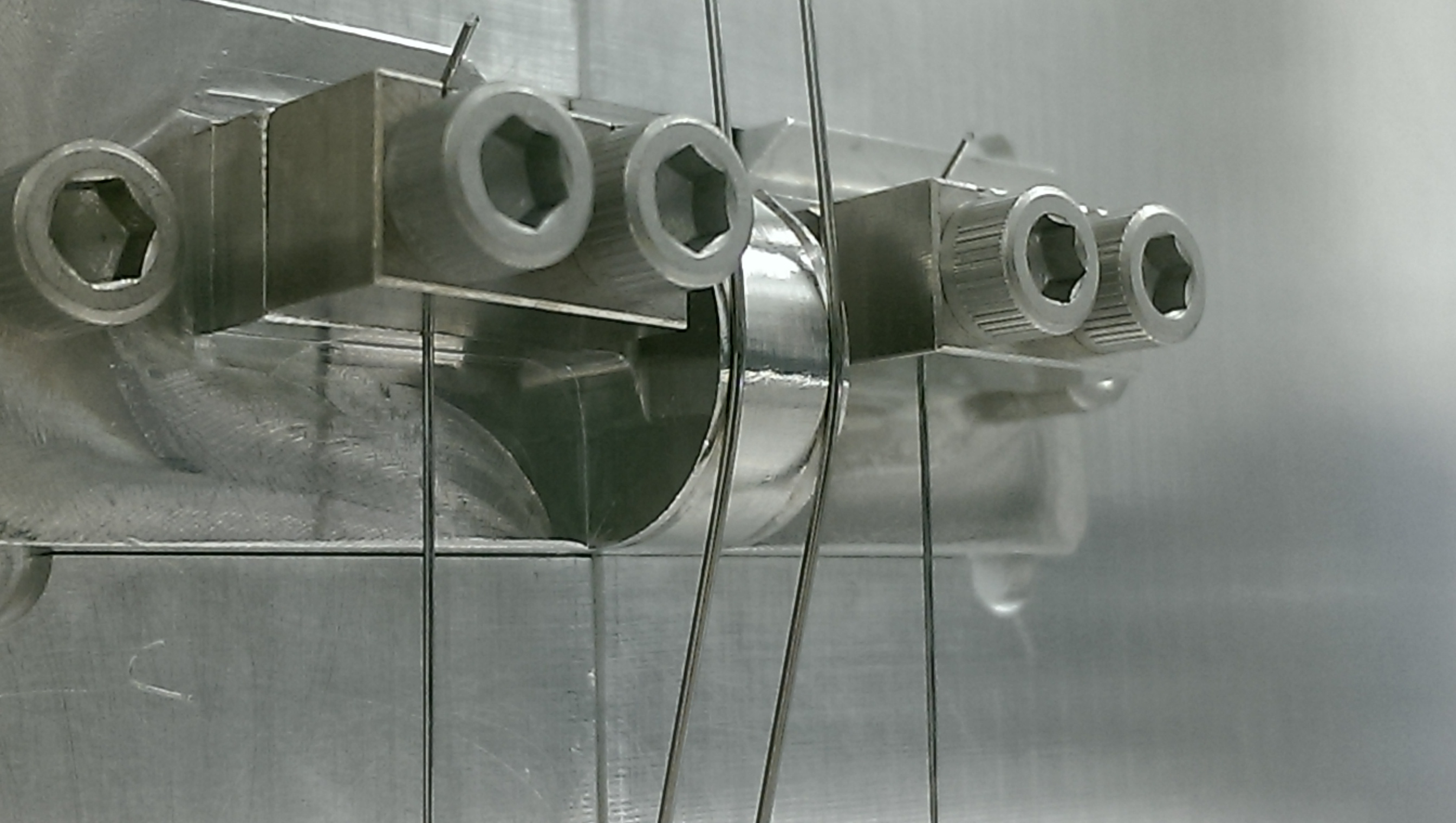
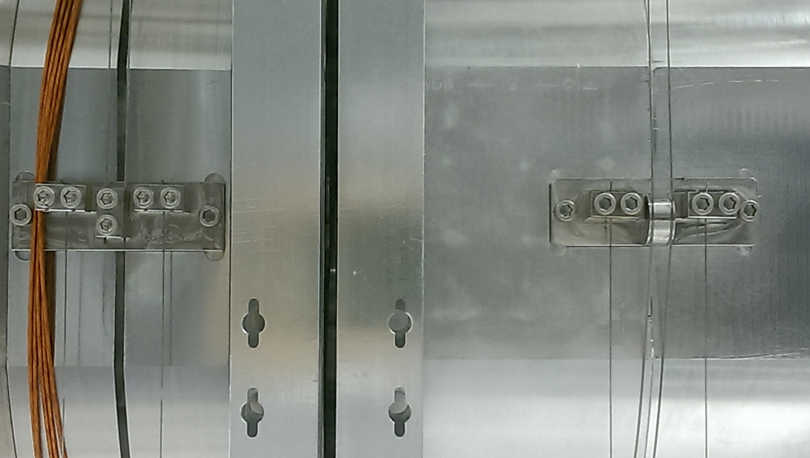
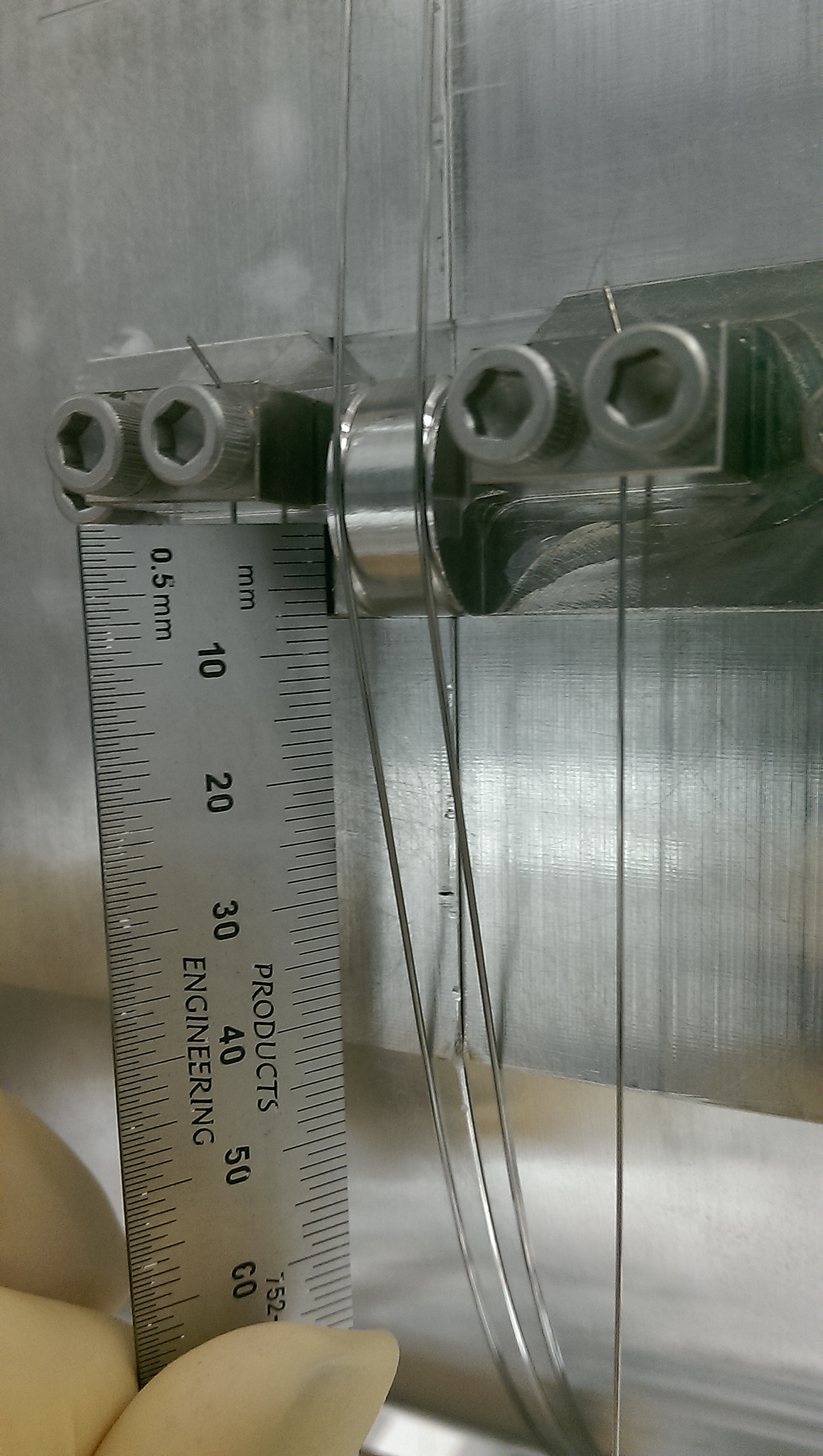
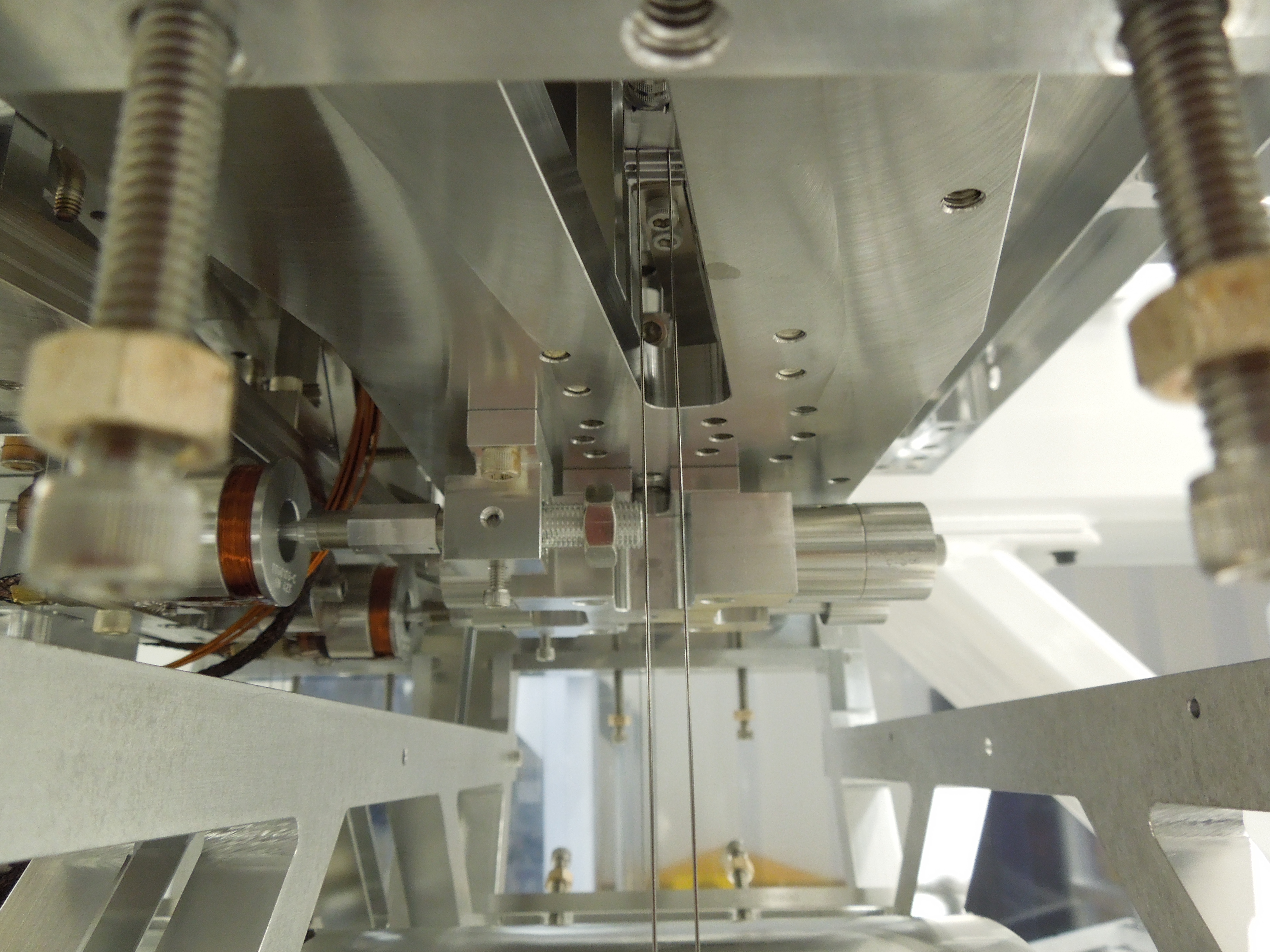
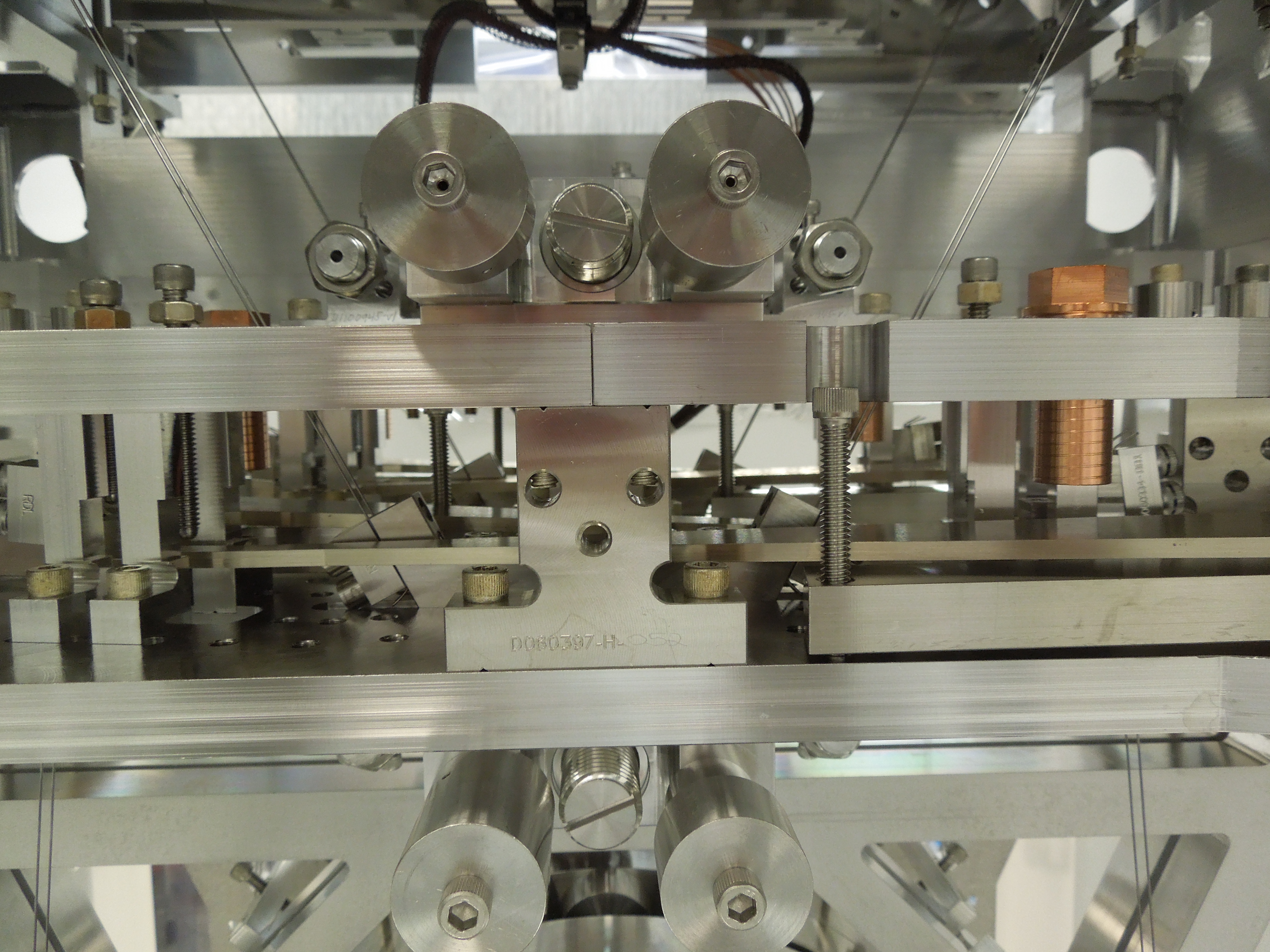
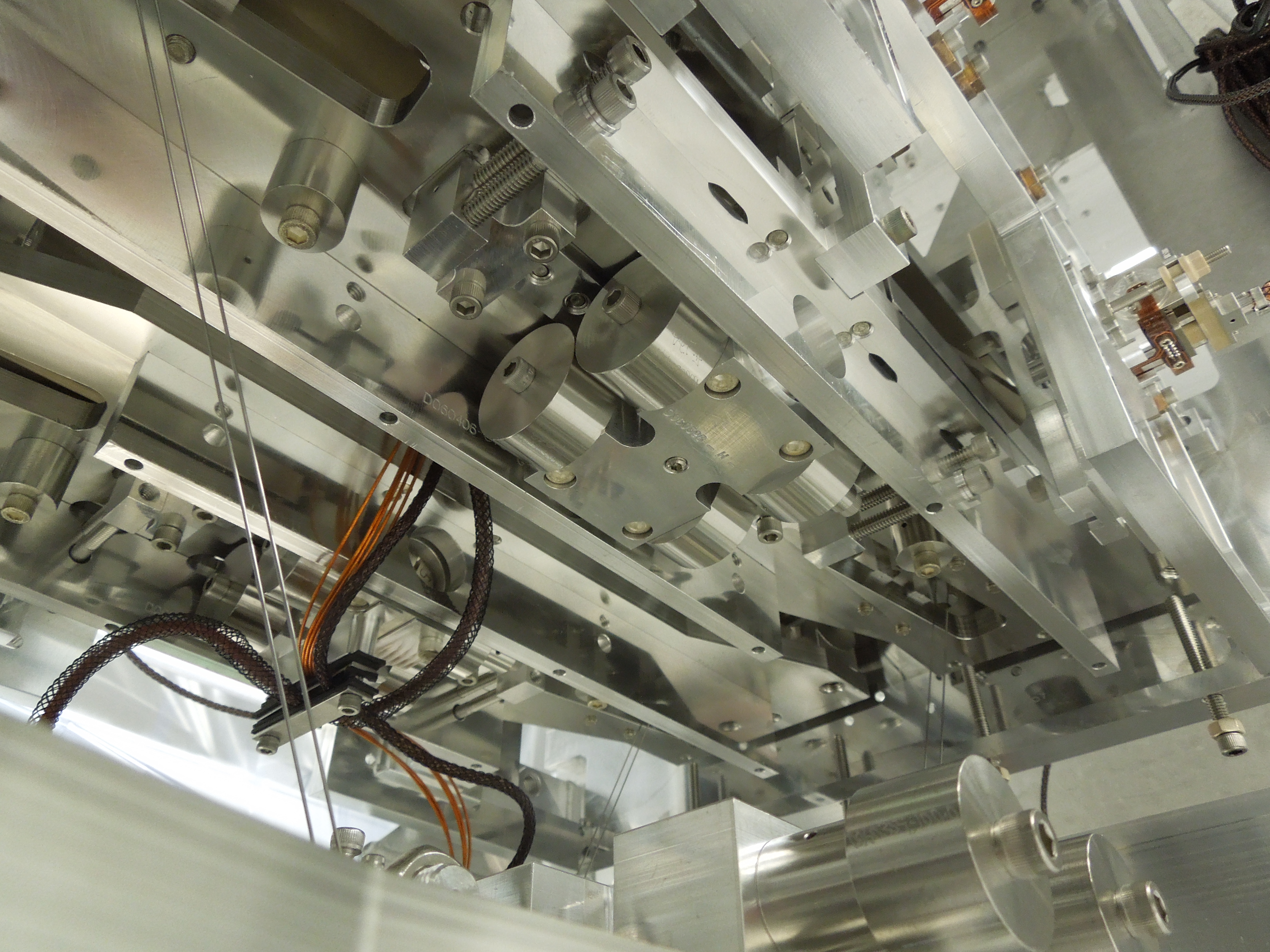
Attachement PUMCOMDetails.pdf is from Eddie Sanchez and is a drawing showing that the position of the PUM wire loop break off in the all metal build is basically the same as where it should be in the final fiber build. However, the model fitting suggests the actual break off is about 1.8 mm lower. So Betsy took some photos of this prism on a suspended metal quad. See image files 1445.jpg to 1447.jpg. Since the prism is round, it could be the wire does not have a clean break off. The pictures seem to indicate the wire has a significant length of a line contact. The 1.8 mm shift could be within this line contact.
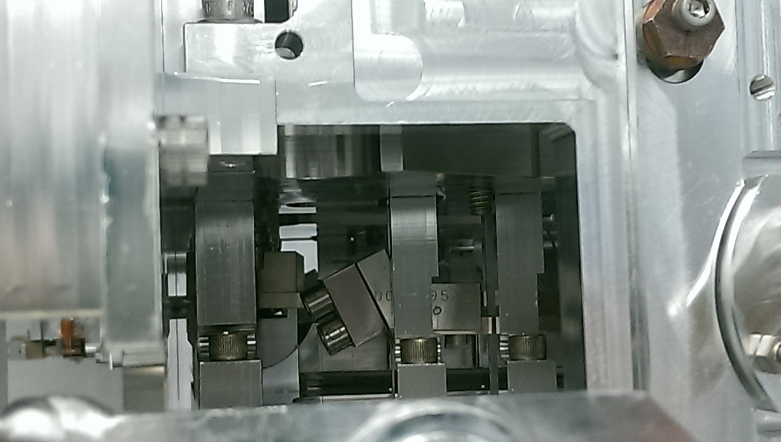
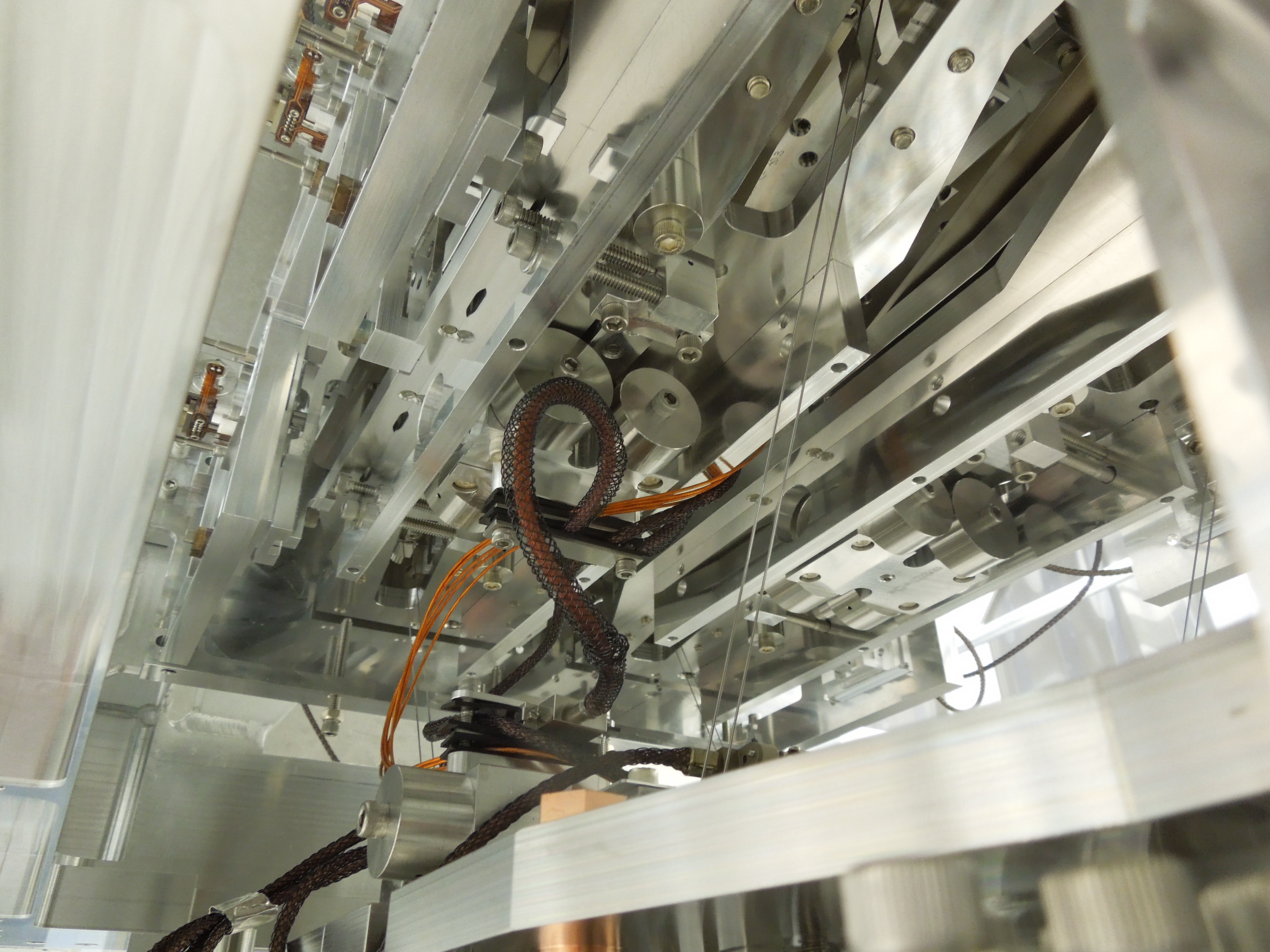
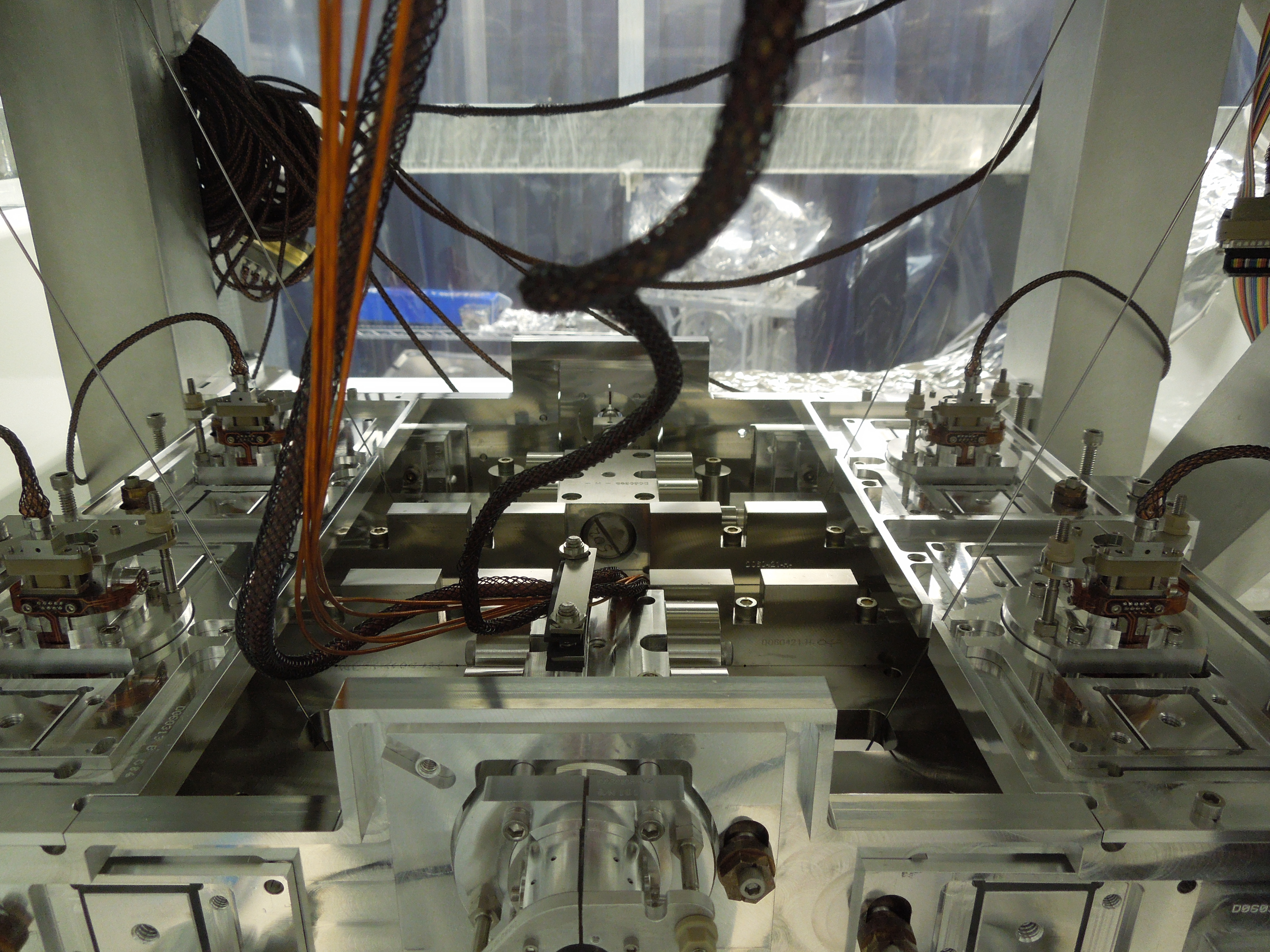
The last image, 1449.jpg, shows a picture of the top mass blade spring tip in a suspended top mass. The spring looks pretty well centered, not consistent at all with +3 mm of apparent shift in dn for this quad. Quoting some numbers from Betsy:
"The top surface of the blade, as close to the tip as possible, is supposed to be at 9.6mm down from the top of the bridge notch. The notch is 14.6mm wide, the blade is 5mm wide, therefore the bottom of the blade should line up with the bottom notch. No gauge blocks needed. From the picture, this looks very close to lining up."