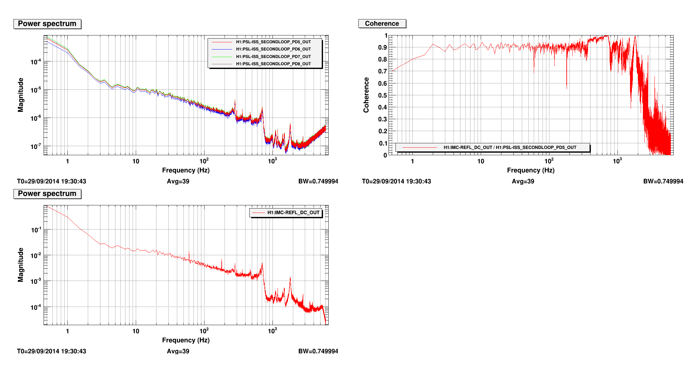
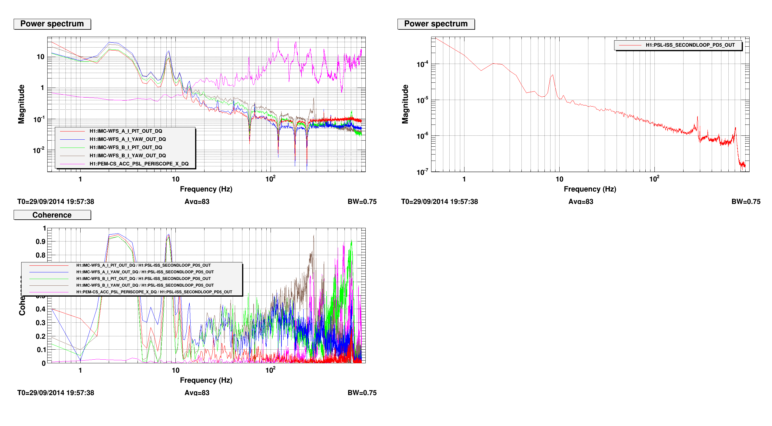
Hugh and I realized this morning (a little late, sorry) that the ISC crew were doing alignments that could be affected by HEPI, which was still locked after chamber close-out. I went down this morning and unlocked, hopefully I wasn't too disruptive. Will attach trends in a bit.
Yesterday we adjusted WFS1 path.
From some calculations by myself and Lisa Barsotti plus an assumption that MC mode cannot be THAT bad, I concluded that there isn't that much of a difference between moving everything to optimize VS moving only RM2.
Detailed analysis will follow shortly, but it seems like we're at not too bad, not too good position and if that turns out to be the case we'll stop here.
For example X waist location is already perfect, the waist size is smaller than ideal and the Gouy separation seems to be 114 deg or some such. Y should be worse.
Before calling it a day, we looked at RMs and one of the eddy current dampers for RM2 was significantly closer to the mirror holder than everything else, so it was backed off.
We took pictures of the REFL path in HAM1 while we were in there, including overview pictures the RM mirrors, the WFS sled, and the REFL PDs. These have been uploaded to ResourceSpace:
After finding a big shift in MC1 pre-pump down to post-pump down, I looked at more optics on both HAM2 and HAM3.
MC3 moved -34urad in pitch and 106urad in yaw. This is consistent with being tilted the same direction as MC1.
PRM shifted -63urad in pitch and 365urad in yaw. This is consistent with tilted the same direction as MC1.
IM4 shifted 98urad in pitch and 82urad in yaw. This is consistent with tilted the same direction as MC1.
Other optics on HAM2 are ignored due to having a shift in position that negates their pitch and yaw signals for this purpose.
The shift in all of these optics show that the +X,+Y corner of the HAM2 optics table is lower than it was before pump down. This is a problem, since this results in the fixed mirror behind MC1 sending the beam low on MC2 by about 5mm.
PR3 has a signal, X/Y_DEMOD_SIG that seems to come from an optical lever. I didn't get a chance to really look into this signal and how it is generated and calibrated. It shows a shift in pitch that's small, but a shift in yaw of 40 counts(?). This supports a rotation of the HAM2 table, though I can't put a real number on it at this time.
I also looked into the IMC WFS and compared a good IMC alignment from September to the lock yesterday. Were all optics table positions restored after pump down to their previous positions, the position of the IMC optics would be very similar. In the current situation, with the WFS drive optimizing the IMC, the optimal positions for MC1 and MC3 have change a lot.
MC1 has changed position by 674urad in pitch and 958urad in yaw. This corresponds to a change in pointing at 16m of 11mm in pitch and 15mm in yaw.
MC3 has changed position by 723urad in pitch and 1030urad in yaw. This corresponds to a change in pointing at 16m of 12mm in pitch and 17mm in yaw.
MC2, in comparison, has changed position by 124urad in pitch and 173urad in yaw. This corresponds to a change in pointing at 16m of 2mm in pitch and 3mm in yaw.
Punchline:
HAM2 - very different than before pump down - tilted and possibly rotated
HAM3 - changed, but may be tolerable long term to the IMC
[Dave Arnaud]
Following Stuart's change at LLO after he discovered a bug in the display of some DAC channels (see alog entry 10101) the directories containing the SUS_CUST_${sus_type}_DAC_MONITOR.adl files have been svn updated, and now displaying the right signal.
Angus, Travis, Gerardo & Alastair Removed test mass from suspension and stored in tin. Small chip on the side of one of the ears on this mass due to brush against structure on removal. After TCS had replaced ring heater we put the production ETMY into the suspension ready for full alignment tomorrow morning. We checked the profile of the fibres in storage and the following ones all look to have approximately the same stretch. S1301759, S1301769, S1301770, S1301771, S1301772 & S1301767. The first 4 of these are now at at end-Y ready for use.
Addressing "Bug 256", the pair of ring heaters installed at the pilot ETM were from Production Lot #1. These have been replaced with a pair of ring heaters from Production Lot #3. See also T1300463-v17.
(Alexa, Sheila)
1. Input to MPC @ MSR: 280uW
2. Output of MPC @ MSR: 240uW
3. To EX @ MSR: 170uW
4. Output @ EX: 45uW
5. Outpt of patch panel on ISCTEX: 42uW
6. On table @ fiber output: 25uW
This is not good. . The loss between 2&3, 3&4, 5&6 are much higher than expected.
If you are measuring the total power, then you might try mandrel wrapping the fiber at the input; it may be that you are measuring power from higher modes in the fiber that will dissipate rapidly in the first part of the fiber chain. A mandrel wrap will dissipate these modes early, so you will be left with a more accurate reading of the power that will propegate the full length of the fiber. This will be particularly true for 1064nm light; singlemode fiber is designed for 1310nm - for 1064nm, it will behave more like multimode fiber.
Even so, something looks particularly bad with the insertion loss for the jumper between the polarizer box and the patch to EX (2&3 in your list). That's probably a bad or dirty fiber.
(Corey, Gerardo)
- Transition of LVEA to laser safe, Justin.
- Chris W, ASC/LSC front end code, per WP4335.
- TCS clean up, Thomas.
- Sheila and Alexa, X-End station, ALS table work.
- Travis, Alastair, Angus, and Gerardo, to Y-End TM removal from monolithic.
- Filiberto, to LVEA, camera work, ITMY installation.
- Transition of LVEA to laser hazard, Justin.
- Restart of epics gateway.
- Mindy and Thomas, Y-End, TCS ring heater installation.
- Travis, Alastair, Angus, and Gerardo, to Y-End, ETM12 install in monolithic.
ETMy Ear Bonding Information: Ear 58 was bonded to side S3 on 9/23/2013. Ear 68 was bonded to side S4 on 9/24/2013.
(Alexa, Sheila)
We were able to get the retro-reflected beam off of ETMX back onto ISCTEX. We adjusted the PIT and YAW offset of the TMS to the following values:
YAW: -297 (originally -224)
PIT: -3 (originally -13)
ETM offsets remain off
We have improved the mode matching between the outgoing and reto-reflected beam by moving ALS-L7 two inches toward PZT 2. By looking at the iris with a viewer, the shapes and sizes of both beams look good and matched.
We have also aligned the retro-reflected beam onto the PD.
DTT templates for RM2 tfs have been modified to match with the model update. They are called and lived in :
/ligo/svncommon/SusSVN/sus/trunk/HTTS/H1/RM2/SAGM1/Data/2013-11-23_2212_H1SUSRM2_M1_WhiteNoise_${L/P/Y}_0p1to50Hz.xml
The turbo was spun up around noon - setpoints have been restored, vent and purge valves have been closed, and the system is stable. Pressure is currently 1.5 e-5 torr.
The IMC wasn't locking when I came to the control room at 13:30 local. People told me that there was a Beckoff restart. So I burtrestored h1ecatc1plc2 to 9 am this morning. The IMC is now back to operation.
All the nds command line clients (such as minute_trend_cli, second_trend_cli, streamer_cli and others) have been recompiled to fix a bug in which channel lists were not written correctly. This resulted in an inability to accurately report values for any channel that wasn't a float data type. Any users of these tools should use the tools to write a new channel list. Also the Makefile was changed to allow compiling with Ubuntu 12.04.
Valved in the roughing pump at X end ~9:30.
Alexa, Sheila, Cryus, Dave, Arnaud
We went to end X to start working on the table there this afternoon. calibrated the PDs on the table, preparing to set up the PLL. Along the way Cyrus helped us with a problem connecting the End X beckoff computer to SVN (restarting the windows machine) and Dave restarted an epics gateway. We saw that we have half the fiber transmission in the wrong polarization, so we will need to adjust it in the morning. We tried to align the two beams to interfer on the beam splitter, but with only 10uW or so in the fiber beam.
We sent the green beam into the transmon, locked the QPD servos, and set up irises once the ETM and transmon offsets were restored. We then raised the front apperature of the EOM, where the beam seemed to be clipping. This greatly improved the beam shape going into the chamber. After that we looked for the return beam, and could not find it. Arnaud had a look at what might have changed for us. He saw a change of about 40urad in HEPI, but that doesn't seem like enough to explain us completely not seeing the beam.
ISC EX PD Calibrations
Fiber rejected polarization 20uW, 0.23V,30dB gain TI=2000 Ohms, meaning responsivity= 0.19A/W
Fiber transmission monitor- 40uW out of fiber, light on PD too small to measure (we are using the old measurement of the splitting ratio 6%) 0.03V, 2000 Ohms, 30dB gain, gives responsivity 0.208 A/W
Laser IR monitor 0.35mW on PD, 1.68V, 2000 Ohms, 30dB, 0.08 A/W. The beam splitter right before the PD has a spliting ratio of 0.55%.
Green laser monitor (this is the beam rejected from the Faraday, so the power observed here depends on any polarization drift as well). with 53 mW of532 coming out of the laser, we have 0.8 mW on this PD, so a splitting ratio of 1.9%
Fiber BBPD (Fiber A) 0.56mW, 2000 Ohms, no gain, 0.14V responsitivty of 0.125 A/W
[Mark B Chris W Arnaud]
After modifying the tip tilts model this afternoon, I adapted the adl files to match with the new channel names, in order to resurrect the medm screens. The filterfile, as well as the snap file were also adapted. The only thing missing in order for the system to work is to connect the masterswitch, which will be done tomorrow morning. Other than this, everything seems fine, cf screenshot
Details of the process :
* Created a htts folder in /opt/rtcds/userapps/release/sus/common/medm/
* Copied the 42 adl files located in /opt/rtcds/userapps/release/asc/common/medm/asctt in the new htts folder
* Modified their filename from ASC_CUST_TIPTILT* to SUS_CUST_TIPTILT*
* Modified the content of each of them by changing the ASC/asc occurences to SUS/sus and ASCTT/asctt to SUSHTTS/sushtts (except for the IOP channels which were unchanged)
* Modified the sitemap to point out to the correct adl files
* Modified the H1SUSHTTS.txt filterfile that has been generated when installing the model this afternoon, to make it match with the old H1ASCTT.txt filterfile thanks to some magic tricks from Chris
* Created a softlink H1SUSHTTS.txt -> /opt/rtcds/userapps/release/sus/h1/filterfiles/H1SUSHTTS.txt
Bonne nuit !
Now the master switch is connected, RMs medm screens are functioning, as well as the damping
Trends for ETMX HEPI IPS. Not great, but pump down is also going on right now, so these numbers look kind of normal. First 8 plots are local, the remaing are "global" in nm, although there are some doubts about their calibration. Looks like the platform lowered ~.1 mm (which makes sense, because HEPI only has Z axis stops that can only push up on the foot), with much smaller movements in the other axes.