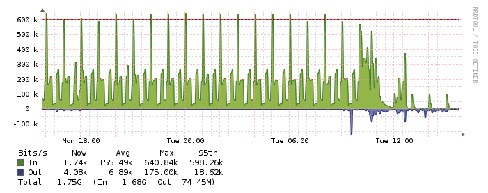
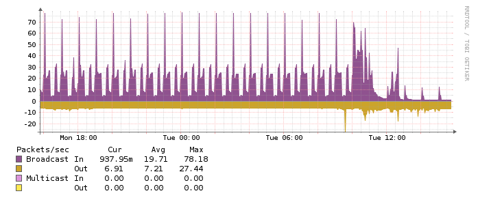
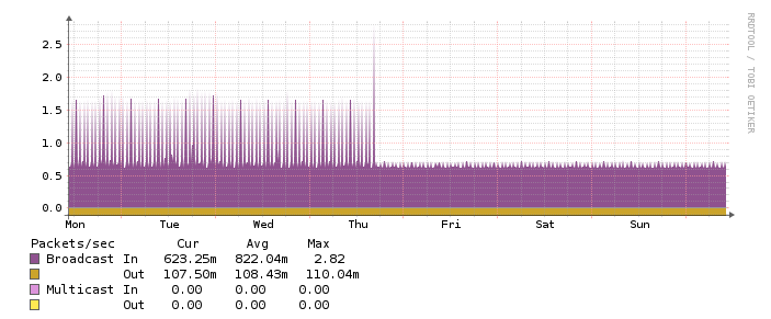
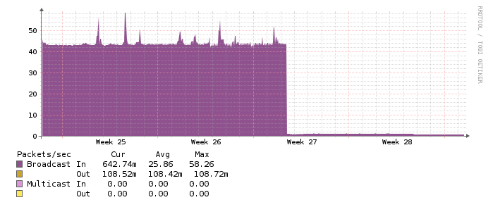
Displaying reports 74361-74380 of 76956.Go to page Start 3715 3716 3717 3718 3719 3720 3721 3722 3723 End
Reports until 15:37, Tuesday 24 April 2012
LHO General
patrick.thomas@LIGO.ORG - posted 15:37, Tuesday 24 April 2012 (2674)
dust monitor code
I am now running new dust monitor code on h0epics2, which is a Ubuntu workstation. It is running under screen.

There has been a bug in the previous code, such that data does not appear to have been recorded since March 15, 2012 for the following:

Dust monitor in clean room over BSC8
H0:PEM-LVEA_DST15_3     any data for counts > 200
H0:PEM-LVEA_DST15_5     any data for counts > 200

Dust monitor in clean room over test stand in LVEA
H0:PEM-LVEA_DST4_3      any data for counts > 200
H0:PEM-LVEA_DST4_5      any data for counts > 200

Dust monitor in OSB optics lab
H0:PEM-LAB_DST1_3       any data for counts > 20,000
H0:PEM-LAB_DST1_5       any data for counts > 8,000

Dust monitor in OSB bake oven room
H0:PEM-LAB_DST3_3       any data for counts > 20,000
H0:PEM-LAB_DST3_5       any data for counts > 8,000

This was because the audible alarms were set for these dust monitors at these levels. When these alarms went off a signal was sent which was read by the CDS code as an error. The CDS code then set the epics channel to INVALID, and the counts were not updated. This should be fixed in the new code.
LHO General
douglas.cook@LIGO.ORG - posted 12:18, Tuesday 24 April 2012 (2678)
Testing First Contact optical qualities when used in a thin file coating
 (Doug, Margot, Jeff)
We setup the Newport laser collimator and retro-reflected the beam from the First Contact thin film coated HR surface and measured the power both in front of the optic and measured the transmitted power through the optics (2 optics and 2 separate measurements) with and without the First contact. Measurements were taken at ~3M and ~6M distance from laser collimator to HR side of sample optics. Sample optics were coated for 1064nm with both HR and AR coatings and First Contact sprayed on the HR surfaces.
I didn't see a need to set up a BS and try to measure a true reflect from the HR surface. The small difference would still be int the absorption and diffused beam if present and is within usable range.
Parameters:
Newport laser collimator beam dia  ~3.0 cm dia.
Ophir power meter aperture 1.2 cm ²

optic s/n 11: @ 3.0 meters
power at 0º incidence in front of optic 44.4µW
power transmitted through First Contact 39.4 µW = 85.6% T
power transmitted through without First Contact 38.0 µW = 88.7 % T (higher reflectivity)

optic s/n 38: @ 3.0 meters and 6.0meters
power at 0º incidence in front of optic 42.4µW
power transmitted through First Contact 36.5 µW (3.0 meters) = 85.6 % T
power transmitted through First Contact 36.4 µW (6.0 meters) = 85.6 % T
power transmitted without First Contact 34.2 µW (6.0 meters) = 80.7 % T (4.9 % higher reflectivity)

No retro-reflections interference noticed.

"This may work"
Doug
H2 ISC
hugh.radkins@LIGO.ORG - posted 12:03, Tuesday 24 April 2012 (2677)
BSC6 ISC Feedthru Inverted and recabled
Apollo (Mark & Chris) pulled the FeedThru (F2-2) to rotate it 180° to put the 'D' right side up in the usual way.  I didn't know the cables were attached and they were unable to pull them far enough out to allow the cable disconnect enabling them to put in a new copper gasket.  I went inside the chamber to disconnect the cables from the FeedThru.  Refer to D1003085 for flange locations and connection descriptions.
Few things here:
1) The In-Vacuum cables on F2-1 have screws for securing to the FeedThru but they were not secured.  I secured them; these would be the ISC-Picomotors & the Transmon 1064nm 25pin cables.

2) The In-Vacuum cables on F2-2 do NOT have screws in the cable and so they aren't secured.  As we flipped the FeedThru and flipped the cables, I felt it prudent to record the cable numbers:
2a) F2-2C1 (ISC Transmon 532 nm) Cable D1000924, S1104106
2b) F2-2C2 (ISC Transmon Beam Diverter) Cable D1000223, S1104077
I did not trace the cables back to the Transmon so don't know from whence they come.

3) While the FeedThru was install upside down from our usual 'D' faces down orientation, my concern about the in-vac cable possibly being installed incorrectly and damaging the FeedThru or Cable was misplaced.  The 25pin cable cannot be installed upside down.  That misplaced concern comes from the 3pin FeedThru where the Vacuum Side can be installed reversed wrt the outside--see the attached photo if you like.
Images attached to this report
H2 CDS
david.barker@LIGO.ORG - posted 10:37, Tuesday 24 April 2012 (2676)
H2 PSL front end and EPICS decommissioned
I have removed the H2PSL from the following systems: H2 DAQ, h2boot and MEDM overviews. This applies to the H2 PSL front end computer and the Beckhoff control and monitoring computers.
This has closed WP3166
H1 PSL
oliver.puncken@LIGO.ORG - posted 22:09, Monday 23 April 2012 (2675)
Disassembly of the PSL (Part 1)
PSL installation team


H1 crystal chiller preparation: 
We found a leakage inside the chiller, which had been fixed now by getting out the flow turbine and preparing it with some teflon tape. Also, the flow has been decreased via the internal bypass valve (It needs to be below 30 lpm, otherwise the chiller would shut down). This valve needs to be readjusted, as soon as everything is connected.

Disassembly of the water supply from the laser head: 
The laser head (oscillator) has been emptied as a preparation step for getting out the pump fibers and (later) the laser crystals. The hoses and the water manifold are already stored in the H1 laser enclosure (but not mounted / connected yet)

Disassembly of the cabeling: 
We started to disconnect the cables on both ends, the racks and the components inside the LAE (laser heads, DBB, etc.)

The oscillator box has been opened unscrewed from the optical table. A big part of the optics between the oscillatot and the DBB and the Amplifier has been removed and stored on a breadboard, such that this breadboard can be moved over to the H1 enclosure. Thus, we are preparing some room on the table to get the transport frame attached to the oscillator (also, these components are needed in the new enclosure anyway.)

The pump light fibers had been disassembled and pulled out from the LAE. They are stored on the floor next to the LAE (the next step will be to get them out of the rail, running above the LAE roof)
H2 SUS
betsy.weaver@LIGO.ORG - posted 16:12, Monday 23 April 2012 (2673)
H2 ITMy BSC8 work
After some serious hunting, Richard tracked the ITMy L2 problem down to the connection on the external side of the feed thru.  It was on the wrong 25 pin feed thru port.  I will re-cable the insides tomorrow.
LHO General
patrick.thomas@LIGO.ORG - posted 16:02, Monday 23 April 2012 (2671)
Ops Summary
Hanford Fire Department on site
Cleaning of OSB bake oven room
Migration of CDS network to new hardware
H2 SEI
jim.warner@LIGO.ORG - posted 15:25, Monday 23 April 2012 - last comment - 16:19, Monday 23 April 2012(2670)
Seismic activities at BSC8
GregG, JimW

Today at BSC8 we hooked up the last of the HEPI actuators, mostly went off without a hitch. Greg should be posting our dial indicator shifts shortly. For future reference, making vertical adjustments to the horizontal actuators can be made with a small bottle jack. Just place the jack on top of the HEPI base clamp and put the top in contact with the underside of the actuator "shelf". 

After the actuators were hooked up, we went inside and looked at the level of the optical table. Need to confer with Hugh about the results, but it still looks pretty good. Could be as good as no more than a 0.1 mm difference across the table. I say "could be", as the measurement was a little difficult to make. It's hard to read a moving ruler through an auto-level.
Comments related to this report
greg.grabeel@LIGO.ORG - 16:19, Monday 23 April 2012 (2672)
We'll have to get some Benzodiazepine for the next time we have to take levels. 

Attaching the horizontals went fairly smoothly. As Jim stated using a bottle-jack worked well for setting the vertical position. The SE corner horizontal actuator has a bound bolt and was somewhat more difficult to set but it went into place without too much trouble as well. A little bit of prying happened on the actuators to get them centered within their bellows. This caused a bit of movement on the support tubes, but not much.

in thousandths of an inch
        NW   SW   SE   NE
ΔV    1d    3d    7d    5u
ΔX    5s    3s    6n    5n
ΔY    2e    3w

This should hopefully translate to less than 25 μrads of cw* movement.

*Edited from ccw Hugh showed me the error of my ways. This is good though because we were out 70 μrads ccw, so we should now be even closer.
Images attached to this comment
LHO General
keita.kawabe@LIGO.ORG - posted 11:21, Monday 23 April 2012 - last comment - 12:14, Monday 23 April 2012(2667)
Chamber cleaning conversation with wise people

A while back I complained about the fact that the chamber, after cleaning, becomes black-ish quickly to various people including  Dennis and MikeZ, and was surprised to know that they didn't know.

I talked with MikeL, RobertS and Jodi since then. This alog just restates what was already known by some experts.

All chambers seem to be covered with black stuff. Attached is the picture of the glove with which I swiped the inside wall of BSC6 last week. Robert looked at it to confirm that it is quite similar to what he saw when he went into BSC8 some time after chamber cleaning to measure the particle count. Jodi also showed me her glove sample from BSC6, which looked quite similar. It's reasonable to say that we're seeing the same oxidization process. Jodi also say that she didn't see this right after the chamber cleaning, but it develops within a few days.

A few notes:

  1. You might think that the thing is grainy, but it's just that the high points on rubber surface are picking up the black thing.
  2. Unlike i/eLIGO days, these black stuff is very fine, and you cannot shake it off of the glove. In i/eLIGO days, when you swipe the inner wall of the chamber, you often had some bigger, scaly thing which you could shake off, on top of something you couldn't.
  3. Since Robert's study referenced above was done after the chamber wall already got covered with this black thing, and since it showed that the particle counts were a factor of 10 smaller than it used to be in i/eLIGO, there's no reason to believe that the particle count is back high again.
  4. I and Robert observed the glove under a microscope, and they're almost pitch black. As far as we can tell the size of the black particles is much smaller than the resolution of the instrument. There were several clumps of black stuff, though.

We don't know if this is going to become worse with time, though, and I think it's prudent to ask Jodi to make an assessment of the chamber surface once in a while, i.e. to go inside, swipe using a glove and a wipe and keep them as samples, and also measure the particle count. Of course she's done these things, but make sure that it's done repeatedly over some time. A perfect opportunity is before we pump down the Y arm, and after one arm test concludes.

There might be other things, e.g. Robert and I talked about wiping a part of the BSC thoroughly clean, have Jodi approve it, swipe using a glove right after that, and leave the glove for a few days to see if it becomes black.

Images attached to this report
Comments related to this report
keita.kawabe@LIGO.ORG - 11:26, Monday 23 April 2012 (2668)

One important thing to remember is this:

No worker should assume that the chamber wall is totally clean.

If your sleeve brushes the chamber wall, you need to at least be aware that your sleeve might become a carrier for the black thing to migrate to somewhere else in the chamber.

If possible at all, in-chamber workers should not touch the chamber.

jodi.fauver@LIGO.ORG - 12:14, Monday 23 April 2012 (2669)
I asked to be the first person into BSC6 so that I could check on this very thing! 

We noticed this phenomenon while cleaning BSC7, the first chamber cleaned with the production procedure. We had the whole chamber wiped down according to the procedure (last wipe for each section should have no visible color) and waited for FTIR results to come back (~7 to 10 days) before we continued to the 2nd vacuum and close out. After the FTIR results came back, we went into the chamber expecting to finish up in short order. But we found that we were seeing black "stuff" on our gloves when we touched the chamber, so the decision was made to wipe down the chamber a second time and then complete the chamber cleaning process. Later, we had to pull the door at BSC7 again (~10-14 days) to follow up on an FTIR result (false positive), and once again, we saw black "stuff" on gloves. FWIW, upon microscopic examination, Rai Weiss found no visible particulate on the "last wipes" that he examined. (If anyone needs me to firm up the number of days between "sampling events", let me know.)

We'll have another good opportunity to assess re-oxidation (or whatever it is) when we do install at HAM 1-2-3. Chamber cleaning was completed at HAM1 on 20 April 2012, HAM2 on 13 April 2012, and HAM3 on 06 April 2012. I predict that enough time will have passed to observe re-oxidation and that initial assessment on re-entry will show black "stuff" on gloves.

I have become interested in a vacuum-compatible fixative for chamber interiors: any one got a viable idea?
H1 INS
jodi.fauver@LIGO.ORG - posted 08:08, Monday 23 April 2012 (2665)
BSC3-2-1 De-install
After lunch on Friday, a crew accessed BSC2 through BSC3 and removed the beamsplitter suspension. The operation went very smoothly: all but four dog clamps were removed, four people supported the sus, and then two people removed the four dog clamps. Slick! Sus was transported out through BSC3 and is now laying on the LVEA floor. 

Since John was in chamber, I asked him to inspect the gate valves so he could comment on their cleanliness.
X1 SUS
stuart.aston@LIGO.ORG - posted 21:24, Sunday 22 April 2012 (2649)
Triple Test Stand Status and PR3 (HLTS) first complete set of M1-M1 tansfer functions
[Stuart A, Jeff B, Jeff G, Jim P, Dave, B, Filiberto C,]

In this entry I aim to capture the status of the triple test stand as it was left, following my week at LHO.

After the initial set-up of the triple test stand (see previous aLOG entry 2639) alignment of the BOSEMs could now be carried out on the M1 stage of PR3 (HLTS), using the real-time medm screen meters. Note that the medm screens are available on the triple test stand under the alias of "sitemap2".

Once aligned, the complete suspension was covered with a canopy to isolate it from the turbulent air flow in the staging building assembly room. It should be noted however, that even after being left for over an hour to settle, during the day watchdogs were still being tripped, M1 OSEM position watchdog occasionally, and OSEM AC watchdog continually. To proceed with testing (actuation and sign checks etc) it was necessary to increase the OSEM AC watchdog from 8000 to 16000 counts. 

In preparation for running transfer functions, the following steps were taken:-

- Configured coil output filters in medm screens (taking note of signs T1200015-v1).
- Generating necessary SUS svn infrastructure for testing scripts, templates, data and results directories for SAGM1, SAGM2, and SAGM3 etc.  

However, while running actuator and sign checks a number of issues were uncovered, such as the default visual representation of the "drivealign" matrices not agreeing with the active functional blocks, resulting with unintentional cross-couplings between dofs. This and other issues resulted in the model being reverted to the last functional LLO version from 5th Jan 2012 (svn up -r 1709), since this is what is believed to be in actually in operation on the LLO triple test stand. All supporting common models were reverted too, compiling and installing went smoothly. n.b. both variants of the model have been compiled on the LHO triple test stand, x1sushxts27 and x1sushxts05 - with the later just needing to be installed when required. 

The largest obstacle encountered by far was the inability to actuate. The user model and IOP models both indicated that coils should be actuating, but no drive signals actually reached the coils. In-line break-out tests were conducted chasing signals from the AI chassis coil outputs to the coil drivers, where the drive signal was being prevented from passing through by the BIO. Configuring the BIO correctly proved problematic and so they were ultimately circumvented (for now) by feeding the coil driver signals directly through the "Test" inputs of the coil drivers chassis.

This enabled testing to proceed:-

- Successfully setting coil output filter offsets (actuating) and checking sensor sign was consistent.
- The required M1 DQ channels were added do the x1sushxts27.ini file, to enable DQ channels for DTT transfer functions to be taken.
- DTT TF templates were updated for X1 sensor and X1 excitation channels.

During working hours it was impractical to try to obtain a full set of M1-M1 TFs. However, post 18:00 (Pacific) environmental noise had dropped sufficiently to allow the first complete set of TFs to be taken. These M1-M1 TFs for the un-damped PR3 suspension can be found below (2012_04_20_1730_X1SUSPR3_M1_ALL_TFs.pdf).

Following the first set of successful TF functions, damping loops were closed, and another set of TFs taken (2012_04_20_1830_X1SUSPR3_M1_ALL_TFs.pdf).

The PR3 TFs obtained look mechanically sound and in good agreement with the model. There is however some excess environmental noise coupling in from 5 Hz and above for some dofs. 

To wrap-up the first set of results for this suspension (and test stand), the data, scripts and plots have all been committed to the SUS svn.
Also, a BURT snapshot has been taken of this functional triple test stand configuration called "20120420_x1sushxts27_PR3" which has been saved at /opt/rtcds3/tst/x1/cds_user_apps/trunk/sus/x1/burtfiles. To avoid any confusion, all other BURT snapshots were deleted, with the changes being committed to the SUS svn.

Finally, I wish to thank the efforts of all those involved at LHO (LLO and elsewhere) in getting this test stand up and running!

Pic 2012-04-19-499 shows the iMac interface to the test stand and PR3 under test (under canopy).
Pic 2012-04-20-509 shows the test stand electronics rack in the staging building lobby.
Images attached to this report
Non-image files attached to this report
LHO General
patrick.thomas@LIGO.ORG - posted 18:47, Friday 20 April 2012 (2664)
plots of dust counts
Attached are plots of dust counts > .5 microns. I have also included a plot of H0:PEM-LVEA_DST12_MODE to show when the dust monitor in the H2 chiller room was disconnected.
Non-image files attached to this report
H2 SUS
deepakmanoj.nandakumar@LIGO.ORG - posted 17:56, Friday 20 April 2012 (2663)
MC1 Assembly Notes

[Jeff B, Deepak K, Andres R and Gerardo M2]

Friday 20th April 2012

 - Assembled all the wire clamps neceesary.

 - The wires for the upper blades were tensed and added to the clamps. Then the were assembled to the intermediate mass.

 - The wires for the lower blades were also assembled in the same manner to the lower blades.

H2 SEI
hugh.radkins@LIGO.ORG - posted 17:48, Friday 20 April 2012 (2662)
BSC6 ETMY ISI Condition--Shrouded & FT Protected, HEPI in run mode and wiring all attached
Eric got the last of the Feed Thrus protected along with the cable strain relief installed.  The HEPI Pier Pods needed to be all plugged in and now that is done.  The dial indicators are in place and we are ready to read them and float the system--Maybe Tuesday...
H2 SEI
hugh.radkins@LIGO.ORG - posted 17:44, Friday 20 April 2012 (2661)
BSC8 HEPI/IAS Update
So we made a tweak of the HEPI to drop the South side and improve our other DOFs in the process.  Following that we reattached the Horizontal Actuators.
This was more that trivial.  The translational moves were large enough that we had to translate the actuators to be able to reconnect them without binding bolts.  So simple but access is poor and it took our crew the rest of the afternoon.  After all connected, a final read of the dial indicators shows we did no harm.
Please hope that attaching the Horizontal Actuators will be similar.
So Monday:
Attach Horz Actuators (Jim & Greg most of morning),
Confirm IAS shots & check Optical Table Level--Adjust with HEPI if required,
SUS tweaks Pitch,
ISI release Lockers & rebalance as needed,
Recheck IAS shots & table level.

Thanks for your support and understanding.

GregG JimW MitchR & Hugh
H2 SEI
hugh.radkins@LIGO.ORG - posted 14:18, Friday 20 April 2012 (2660)
BSC8 HEPI/IAS Update
We've gotten the Optic within tolerance but the Dial Indicators suggest we have pulled the Optical Table out of Level.  We will make a slight adjustment with HEPI to address this level and hopefully further bring the Optic to 0,0,0 position.

Greg, Jason, Hugh
H1 INS
jodi.fauver@LIGO.ORG - posted 19:46, Thursday 19 April 2012 - last comment - 08:15, Monday 23 April 2012(2658)
BSC3-2-1 De-install
The plan of the day was to set a cleanroom over BSC2 so that we could pull the dome at that chamber and de-populate both BSC2 and BSC3, including SEI stacks prior to cleaning either chamber. Unfortunately, reality got in the way: turns out it is impossible to set two regular BSC cleanrooms side by side and have both cleanrooms center over the domes. If the short-sided BSC cleanroom was available, the plan would work but "the special" cleanroom is tied up at BSC8! In addition, there is a limited soft roof supply soooo.... We went with de-install lite: pull the beamsplitter from BSC2 and then de-install at BSC3. 

After lunch, Cheryl and I went in to document the condition of the optics and chambers. Cheryl took lots of pictures. The highlight (or low light) of the initial inspection was the elliptical baffles in BSC3 and BSC1. The side of the black glass facing away from the optic has both a very fine layer of particulate and then an overlying of larger particulate. There seem to be features associated with gloved fingertips touching the glass: it looks like the oxide from the chamber interior may be differentially attracted to these spots. (I'm sure Cheryl will attach pix when she gets a chance.) On a brighter note, the side of the glass that faces the optic looked quite clean. We found the usual metal fines, a few fibers, etc. on the suspensions. Of the three chambers, BSC2 appeared to be the dirtiest. I took a wipe sample from the chamber bottom and collected two clumps of fibrous material there. We looked at bellows convolutions: BSC1 was atrocious as it contained a couple areas that looked like chunky mucus and some small shards of what looked like black glass. We saw the usual mess at gate valves with particulate accumulated onto rollers, large particulate gathered up in all the low spots and lots of smaller particulate on all flat surfaces. There is even a very long fiber (~2 inches) down in BSC1's gate valve. (I'll try and collect it when we chamber clean there.)

Once we were finished, Michael L, Chris S, and Kiwamu went in and retrieved the OSEMS and beamsplitter from BSC2. 
Comments related to this report
cheryl.vorvick@LIGO.ORG - 08:15, Monday 23 April 2012 (2666)
Pictures attached in a pdf.
Non-image files attached to this comment
Displaying reports 74361-74380 of 76956.Go to page Start 3715 3716 3717 3718 3719 3720 3721 3722 3723 End