As preparation for automating the initial alignment, I did some things associated with the X arm locking.
(LSC-TRX_A_LF path was realgined at ISCTEX)
After the PSL light was locked to the X arm, I realigned TRX_A_LF path in order for LSC to be able to do triggered lock acquisition. The beam was already hitting the center of the bottom periscope mirror from the beginning. I steered the bottom periscope mirror and some optics in the down stream. I found that a lens had been taken out presumably due to the previous QPD work in this past July (see alog 12672). There was a post holder and a base plate secured on the table in front of the bottom periscope mirror. Looking around, I found a 2 inch lens (PLCX-50.8-515.1-UV-1064) with a post laid on the table. So I inserted it to the post holder and looked this was the right lens as the beam nicely converged towards the photo-diode (Thorlabs PDA100A).
Also, I put a temporary steering mirror aside. This is one of the mirrors that Sheila placed in this past July (alog 12672) and has been blocking the PDA100A. The DC voltage coming out from the PDA100A was about 300 mV with a 00-mode transmitted light on it. I did not check the gain setting of the PDA100A. The ADC count reached 1x10⁴ cnts when the arm was locked on a 00 mode. Probably we will need to decrease the gain of the PD or that of the interface box at some point in the future in order to aviod saturation.
In addition, I adjusted the trans camera. I needed to move a black-place beam dump closer to a beam splitter which is the one before the PDA100A. Then I steered the beam splitter and the angle of the camera to coarsely center the beam in the view. I could not identify the channel number for this signal at the video matrix in MSR. Looks like channel #53 is it, but it keeps flickering for some reason and therefore hard to tell. Though, a 00-mode beam was visbile ocasionally. We need to fix this in the day time tomorrow.
(IM4/PR2 alignment with REFL9 WFS)
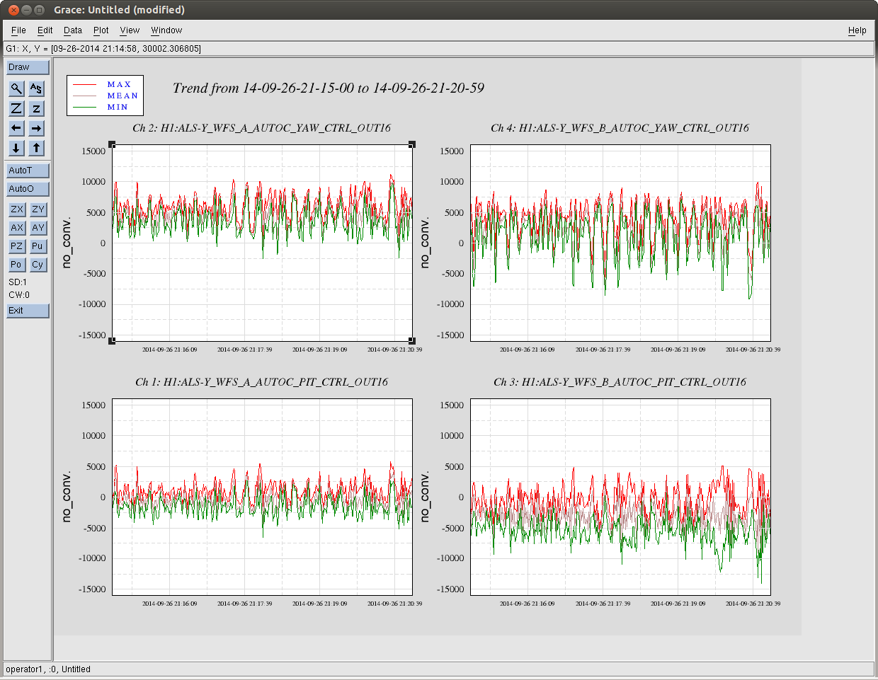
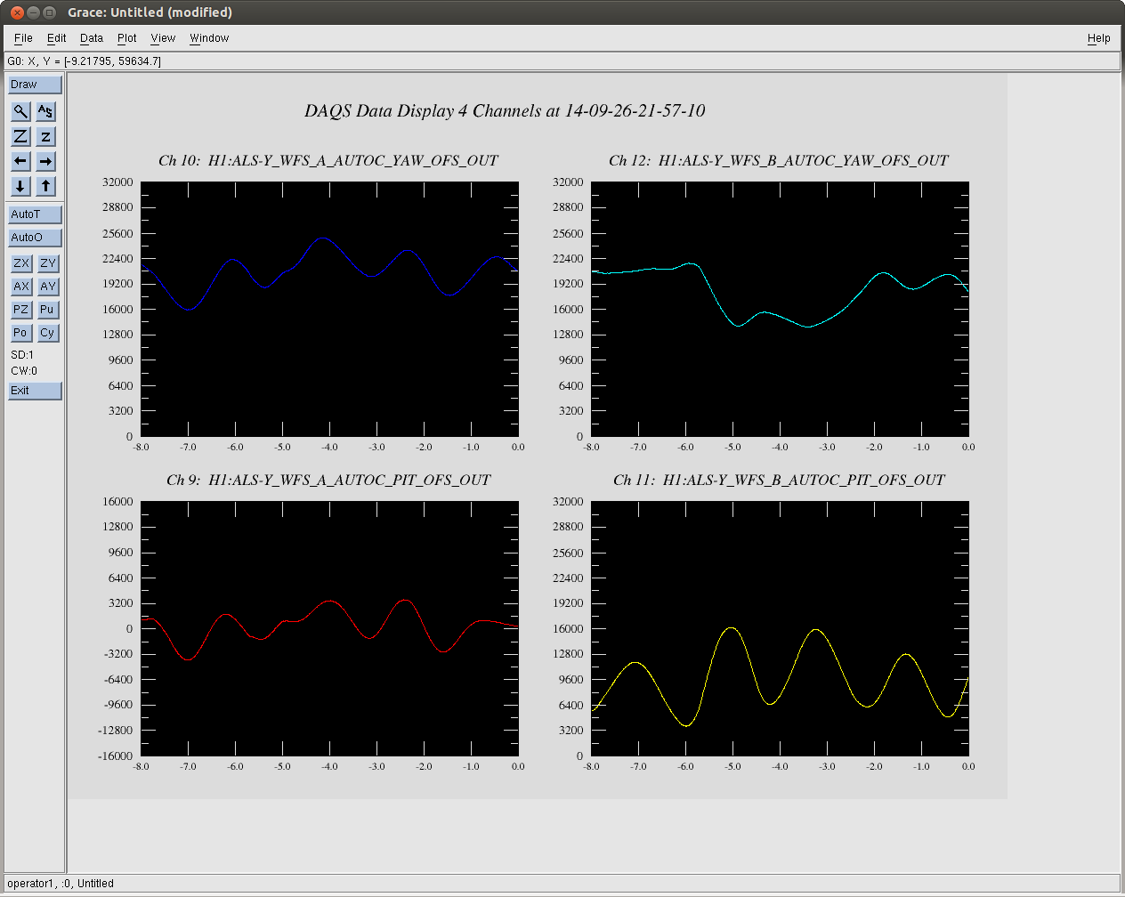
Instead of aligning IM4 and PR2 by hand, I started doing it using the REFL WFSs. I used REFL_RF9_A and _B and they worked well. Once I zero-ed the electronics offsets in the RF9 demodulated signals,they started looking reasonable. I closed two loops by feeding the A_RF9_I signal to IM4 and the other to PR2. IM4 turned out to be a well-diagonalized actuator in the sense that it was able to actuate mostly on the WFS_A signals. On the other hand, PR2 had some cross-coupling which is not surprising at all. I need to work on this a bit more in order to have more diagonalized servos. I did not precisely adjust the gains. So these are the remaining tasks.
Anyway, closing the loops increased the transmitted light and reduced first-order coupling from angular fluctuation of some optics. Note that I had the DC centering servo running in order to keep the spot centered on both WFS_A and _B.