Keita, Sheila, Gabrielle
-
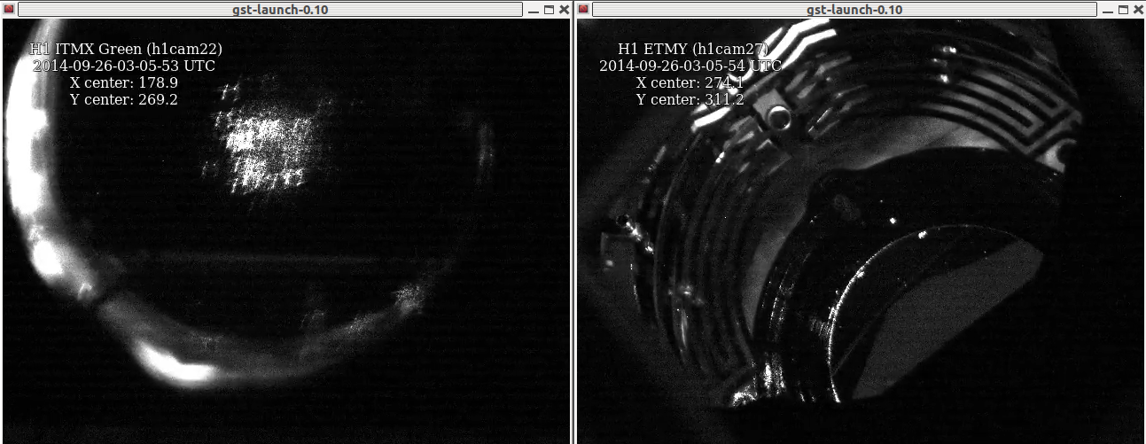
We have a single shot beam from TMSY onto ISCT1, with 10uW of light, we have a beam from the ITM in the end station, and we have a second beam from ETMY on ISCT1.
-
Positive pitch is in the opposite direction on the ETMY alignment slider than on the TMSY alignment slider (I believe that TMS is the incorrect one).
-
There seems to be a mix up with the baffle PD cabling.
-
The ALS Y GigE camera has a softaware problem: the exposure cannot be changed from 2168317875, even though auto exposure is off.
Now, in chronological order:
result of TMSY to IMTY baffle PD search:
|
PD label in epics
|
PIT |
YAW |
V |
gain (dB) |
|
ITMY PD1 |
2.2 |
7.3 |
3.6 |
20 |
|
ITMY PD2 |
-72.5 |
-70 |
4.3 |
20 |
|
ITMY PD3 |
-153.5 |
-1.6 |
|
20 |
|
ITMY PD4 |
-97.8 |
74 |
3.6 |
20 |
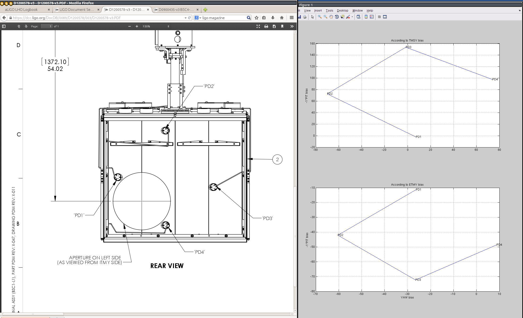
Based on D1200657-v4, (assuming the view shown is looking at it from the BS), this does not make sense with the arrangement of baffle PDs. These votlages are low compared to what we see on the X arm, so we suspected that this was a second bounce or ghost beam, however, they do not move when the ITM or ETM are moved, so they are not reflections off of those optics. If we think that if these are the real beam, the baffle PDs are mislabeled somewhere, so we used the TMS suspension alingment sliders to try to figure out which PD is which. (Unfortuately, the TMS alignment slider also seems to be wrong.)
Based on our reinterpreation of the labels, we thought that the beam should be roughly centered on the optic when TMS is at -35 PIT, -31 Yaw. However, we saw no sign of our beam at this location, nothing on ISCT1 and nothing returning to the ETM when we scan the ITM. Keita trended the old values, and we saw the beam go by on SRM when he restored them. Gabriele and I went to ICT1, and found a badly clipped beam by exciting the BS. Later Keita and I returned and moved the TMSY alignment to get a somewhat better beam, with a TMS alignment of -87 PIT and -51.4 YAW and BS at 187 PIT and -258 YAW, we have 10 uW on ISCT1. this was the same in the spring (alog 11296) giving us some confidence that we really have the single shot beam on ISCT1. (This is our first clue that the TMS alingment slider is wrong)
We went through the baffle PD game by moving ITMY and looking at the ETMY baffle PDs, using this TMS pointing which isn't necessarily centered on ITMY:
|
PD label |
PIT |
YAW |
V |
gain (dB) |
|
PD1 |
140 |
-106 |
almost 2V |
20 |
|
PD2 |
112 |
-135.9 |
2 |
20 |
|
PD3 |
140.3 |
-170 |
2 |
20 |
|
PD4 |
173 |
-140 |
2 |
20
|
This seems to make sense, but the power is low again. We think this beam should be roughly centered on the ETM with the ITM slider at 156.5 PIT -123 Yaw.
Since exciting the ETM (around its saved alignment) and watching on the MC1 camera and at ISCT1 didn't show us any return beam, we redid the baffle PDs for the ETM pointing:
|
PD label |
PIT |
YAW |
V |
gain (dB) |
|
PD1 |
11.3 |
-26.3 |
0.17 |
0 |
|
PD2 |
42.0 |
-60.4 |
0.21 |
0 |
|
PD3 |
72.3 |
-26.6 |
0.17 |
0 |
|
PD4 |
48.5 |
8.8 |
0.18 |
0 |
This beam also did not make sense with the baffle PD arrangement, or our interpretation of the actual PD arrangement based on the TMS alingment sliders. This means that either ETMY or TMSY has a sign flip in the pitch alignment slider (our second clue):
|
label |
reality according to TMSY |
reality according to ETMY (I think this is the correct case) |
|
PD1 |
PD4 |
PD2 |
|
PD2 |
PD1 |
PD1 |
|
PD3 |
PD2 |
PD4 |
|
PD4 |
PD3 |
PD3 |
Once we understood this I decided that our ETMY interpretation of the cabling must be the correct one, since the TMS pointing that actually gets a beam through the optic is very different in pitch than the pointing we calculated based on the baffle PDs. Using this information, our original TMSY centered pointing should have been -113 PIT, -35 Yaw. Indeed, this pointing does result in a beam that doesn't look clipped on ISCT1. I can also see two other beams on ISCT1 which come from the ETM, but haven't been able to easily align the arm cavity. Although I see some fringing, the mutliple bounce beams seem to get clipped as I try to align them. I think the next step is to start fresh with baffle PDs, now that we think we know which one is which.