Borja
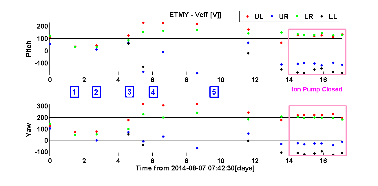
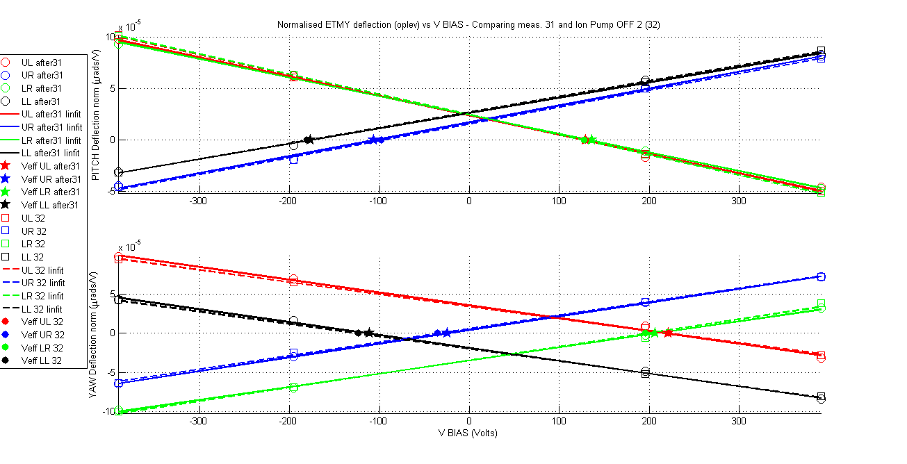
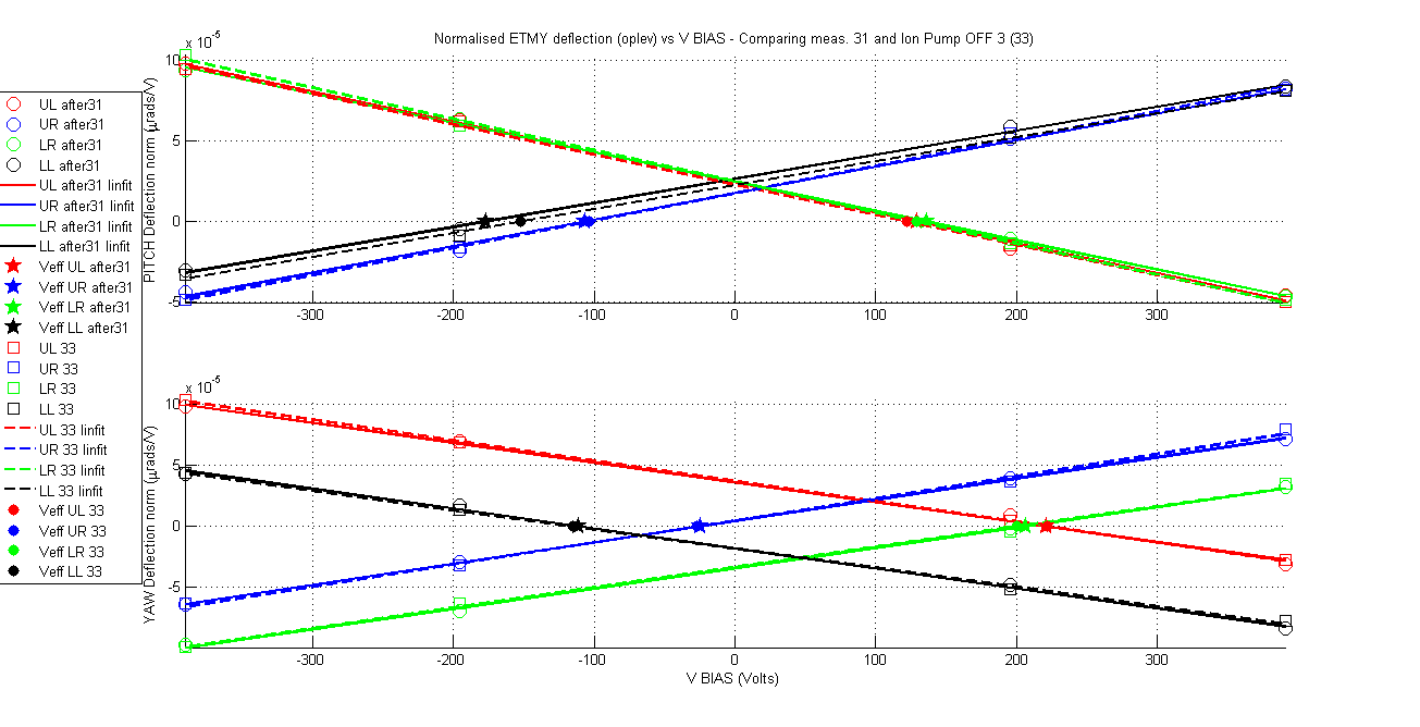
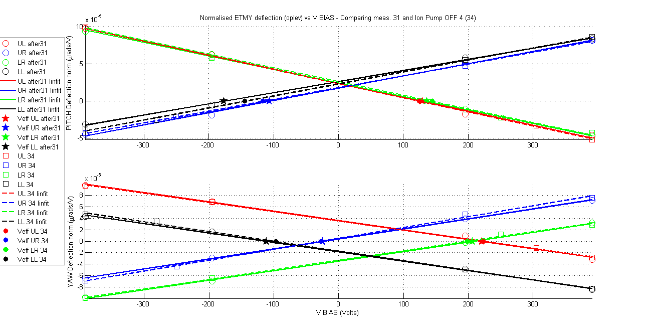
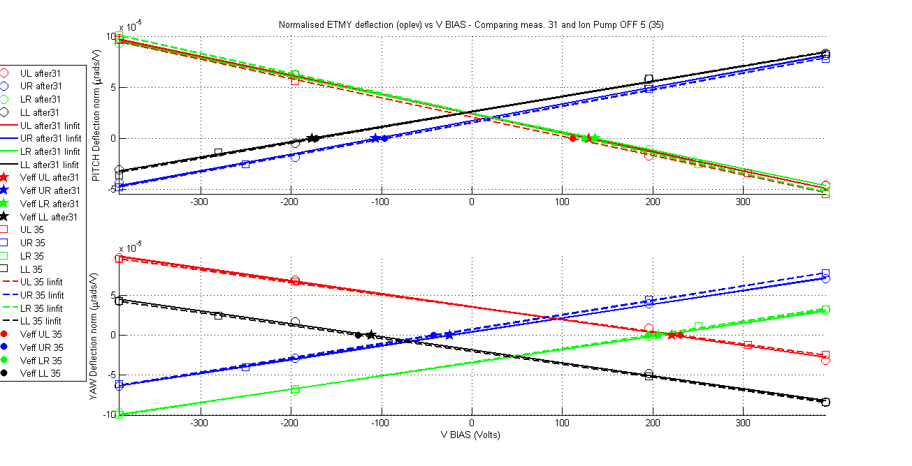
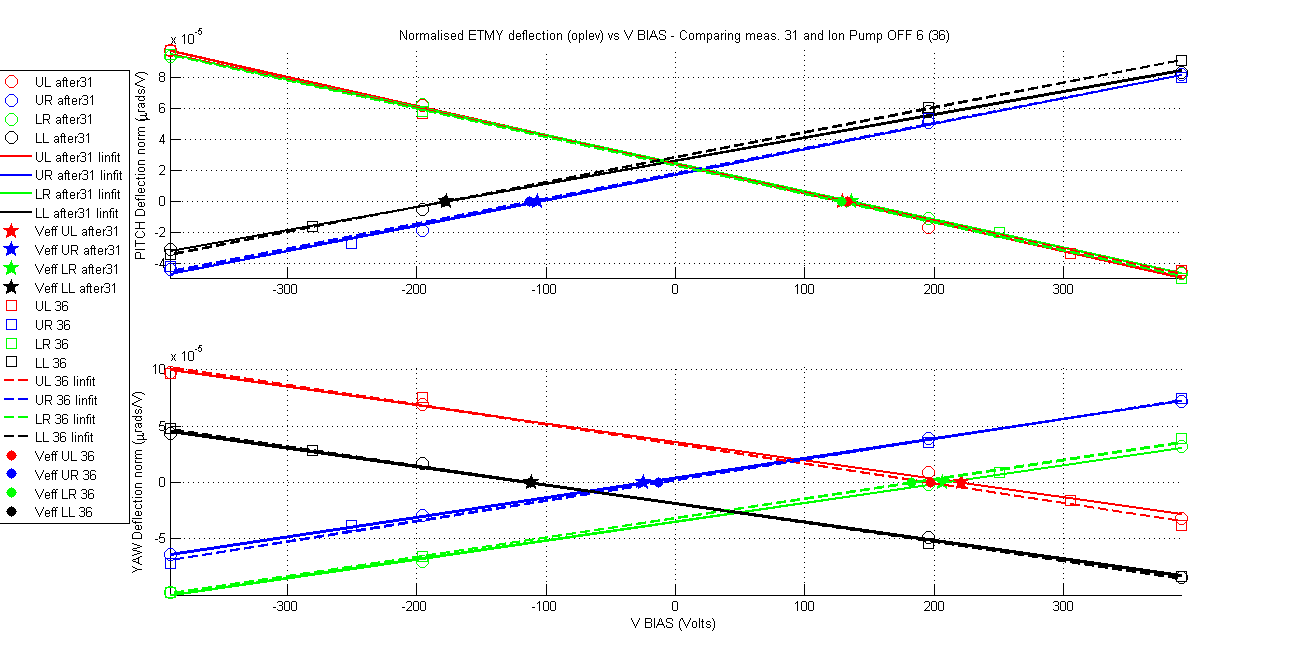
Yesterday's results in ETMX although positive from aLIGO operation point of view (no charging mechanism was observed based on green light and ion pump) however it was discouraging from the point of view of providing answers to the big charge changes that were observed in ETMY. If the ion pump was not charging the mass then what was doing it? Is this unexplained behaviour in ETMY charge changes casting a shadow over the charge measurements methodology? Fortunately a new set of measurements in ETMY that were taken during the experiments at ETMX confirms that the measurement method is reliable and it also tells us what is charging ETMY. For a period of 62 hours 6 charge measurements were taken on ETMY, for all these measurements the ion pump gate valve was closed. The results are remarkable in their consistency and stationarity of the charge values for all quadrants and for both orientations (pitch and yaw) within no more than 20Volts (less depending on the quadrant and orientation). The charge values agree with the last measurement taken just before closing the ion pump gate valve.
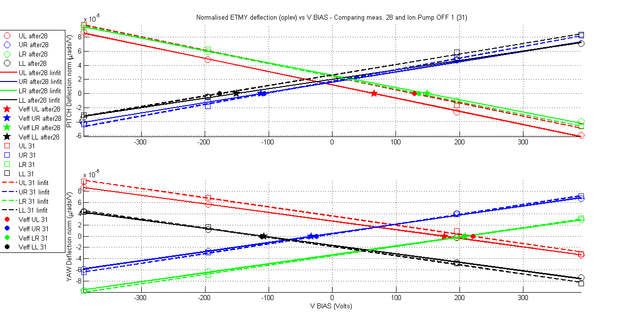
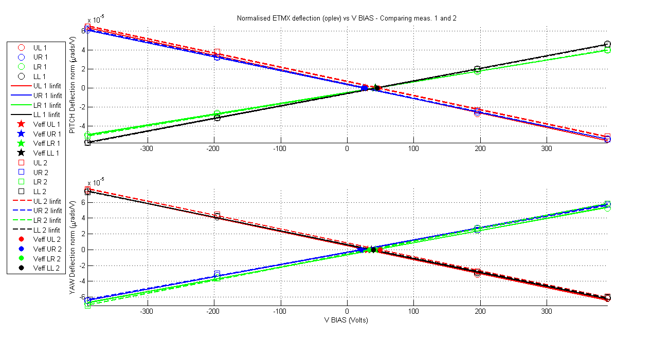
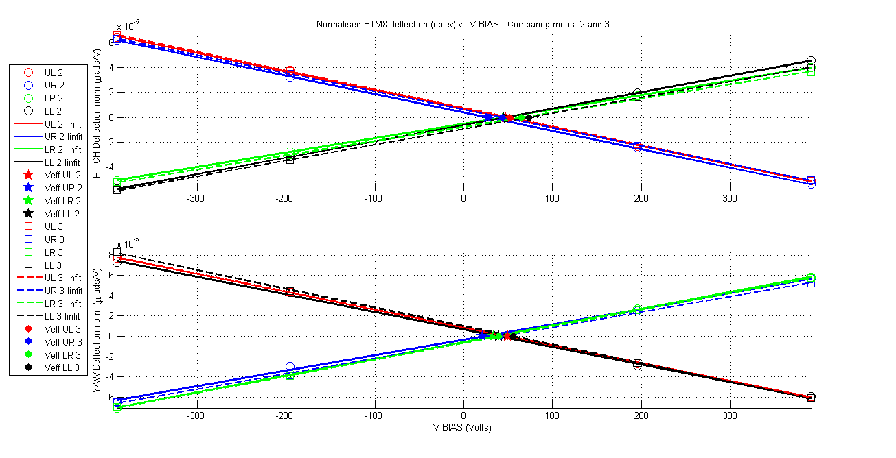
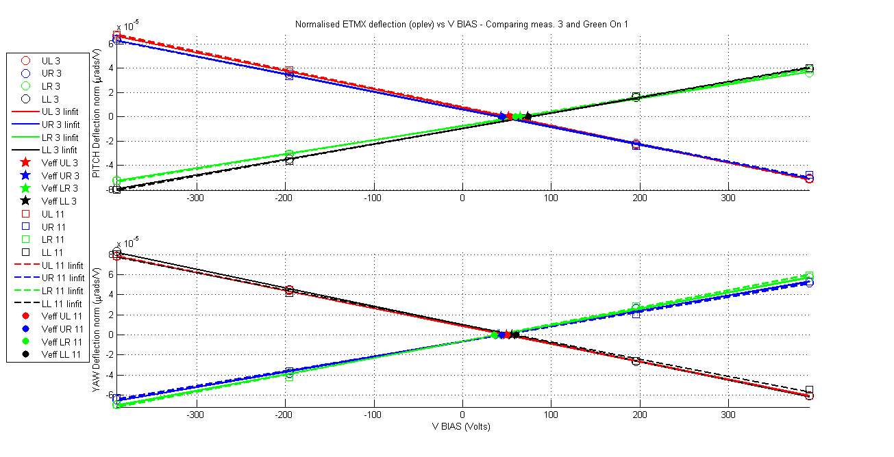
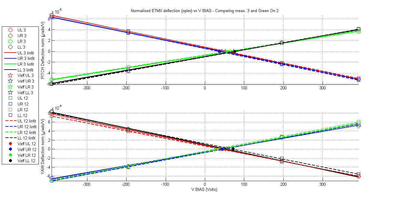
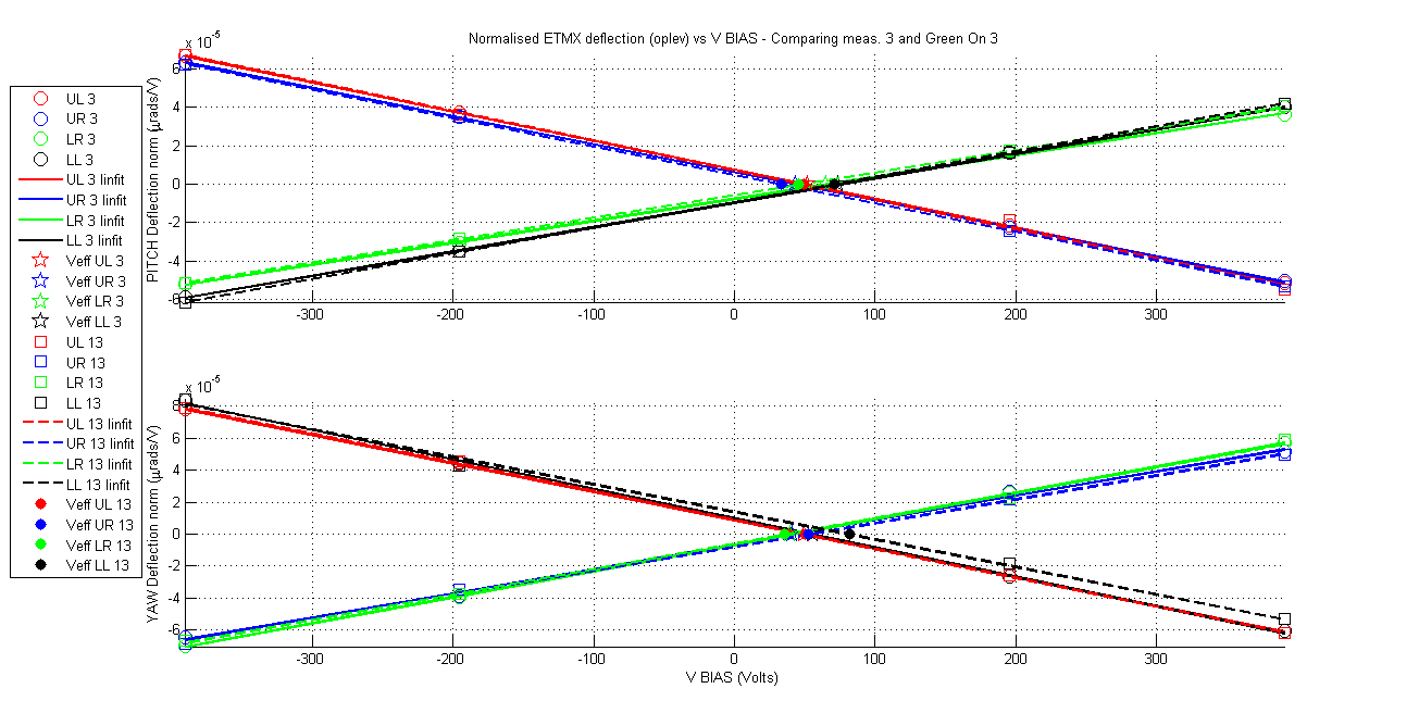
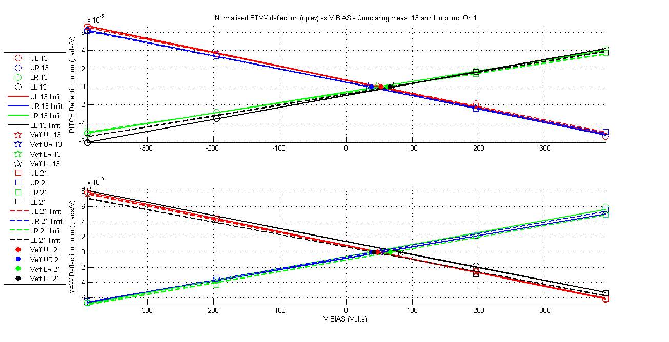
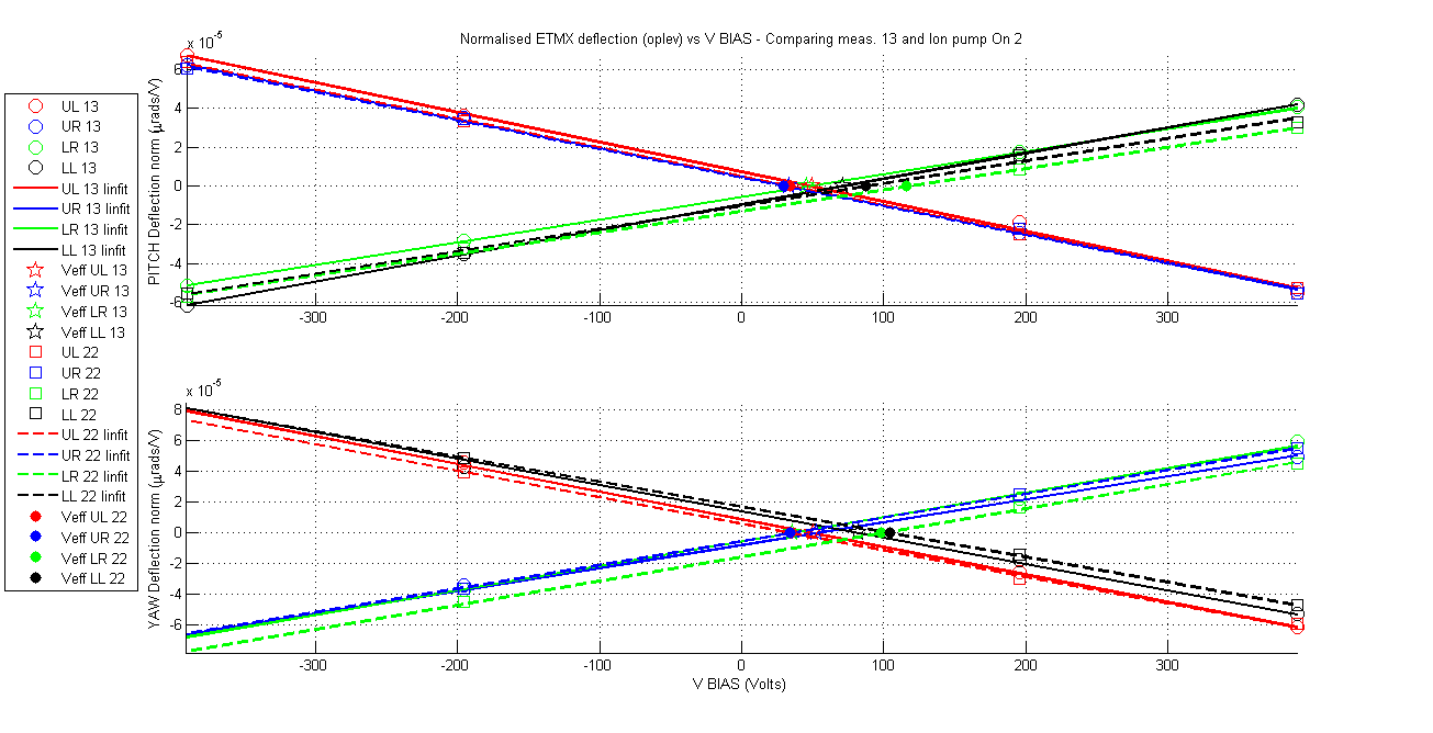
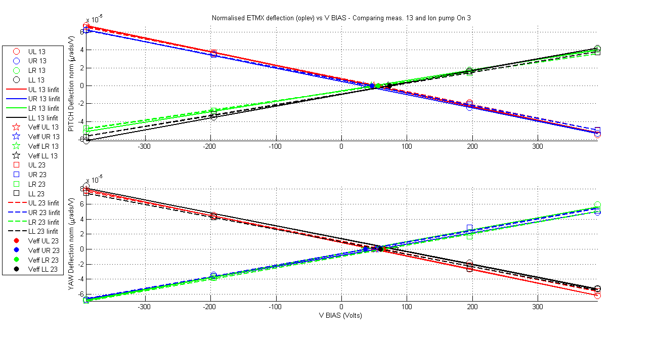
The amount of measurements make it impractical to show a summary table like in my previous aLog so this time I go for a more friendly graphical display. As always attached are the measurement documents and the standard VBIAS vs normalised deflection plots comparing each measurement with the ion pump gate valve closed with the first one, and the first one with the one previous to closing the valve.
So what is different between X and Y regarding the charging effect of the ion pump? mainly 3 differences:
1) The Earth magnetic field
2) The pressure being different by an order of magnitude. The pressure in end-X is 2.7e-7 torr while in end-Y is 4.8e-8 torr. A higher preasure will reduce movement of the ions, but at the same time the higher the pressure the more charge is emitted by the ion pump (see attached document "charged_particle_emiss_ion_pumps.pdf").
3) Both ion pumps were costume made to the same specifications. They are made of 50 smaller ion pumps so maybe the way these were configured is different for each final ion pump.
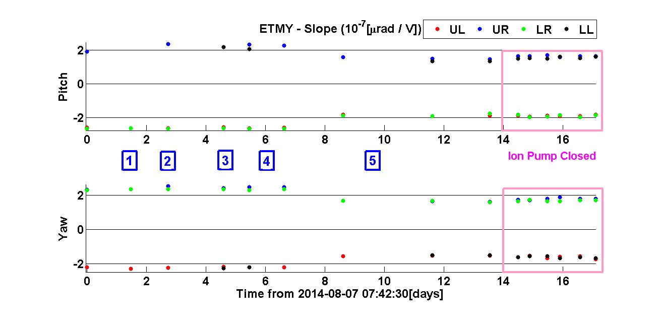
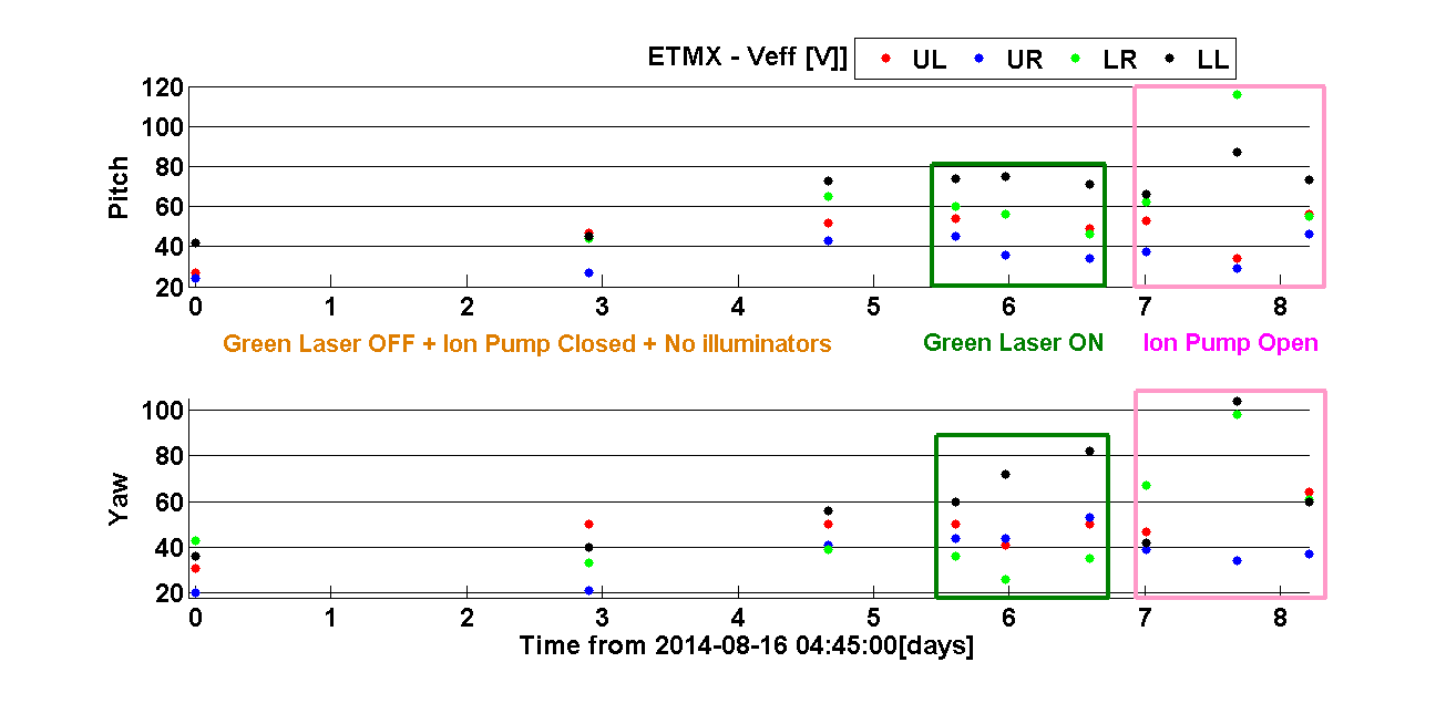
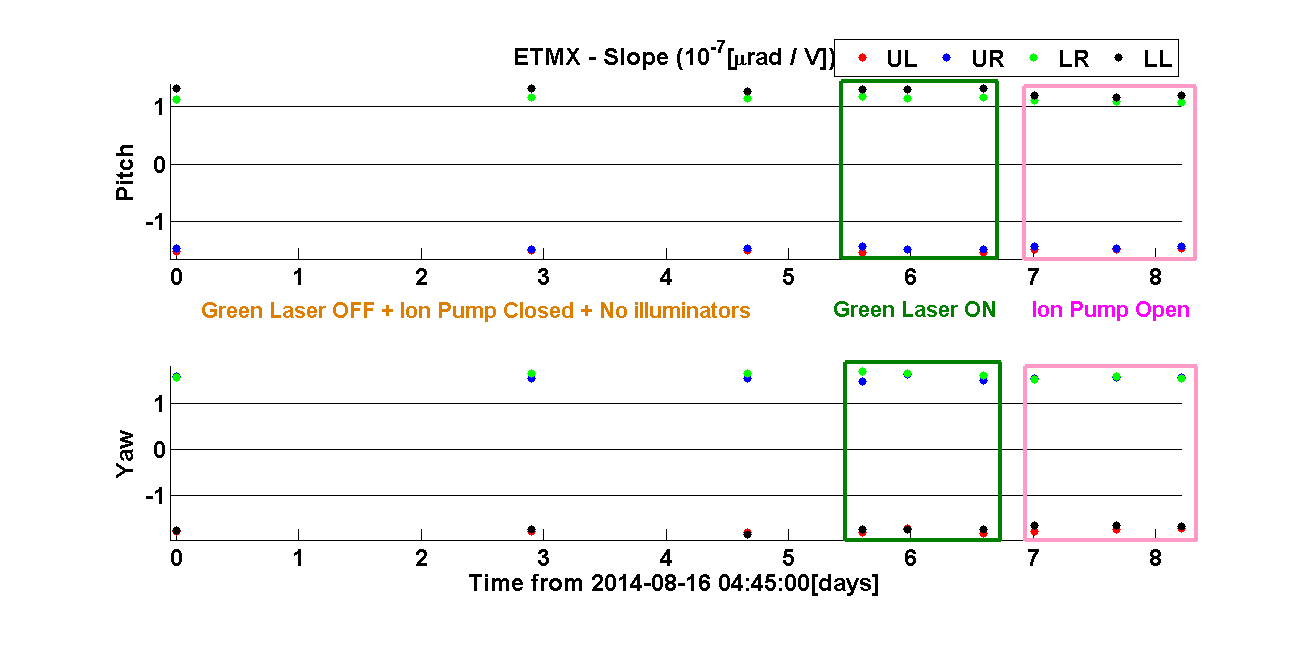
Next I show the summary plots of all measurements taken so far both for ETMX and ETMY. Each mass has 2 set of plots; Veff and slope of normalised deflection vs VBIAS. Each set of plot is divided in 2 subplots, one per deflection orientation (pitch and yaw).
ETMX:
ETMY:
The numbers in the plots represent the major changes that took place at the time of the measurements. These are summarised next:
1) 1st ionizer discharge.
2) 2nd ionizer discharge.
3) Wire swap to right configuration: BIAS going through the ESD LP filter box.
4) Wire swap to wrong configuration: LL quadrant driver going through the ESD LP filter box.
5) Wire swap to right configuration and Final: BIAS going through the ESD LP filter box.