Alexa, Rana, Sheila, Kiwamu,
We locked the DRMI tonight for the first time. It could stay locked for more than 10 minutes.
(A prep: PRMI locking with REFL signals)
Before moving onto the DRMI locking, we wanted to lock the PRMI on the sideband without using the AS detector. We first locked the PRMI with the conventional sensors i.e. REFL9_I for PRCL and ASAIR_45Q for MICH respectively. By exciting and looking at transfer coefficients, we figured out
REFL45_Q = -12.5 x ASAIR_RF45_Q for MICH readout
So, we put 1/-12.5 = -0.08 in the input matrix and this worked.
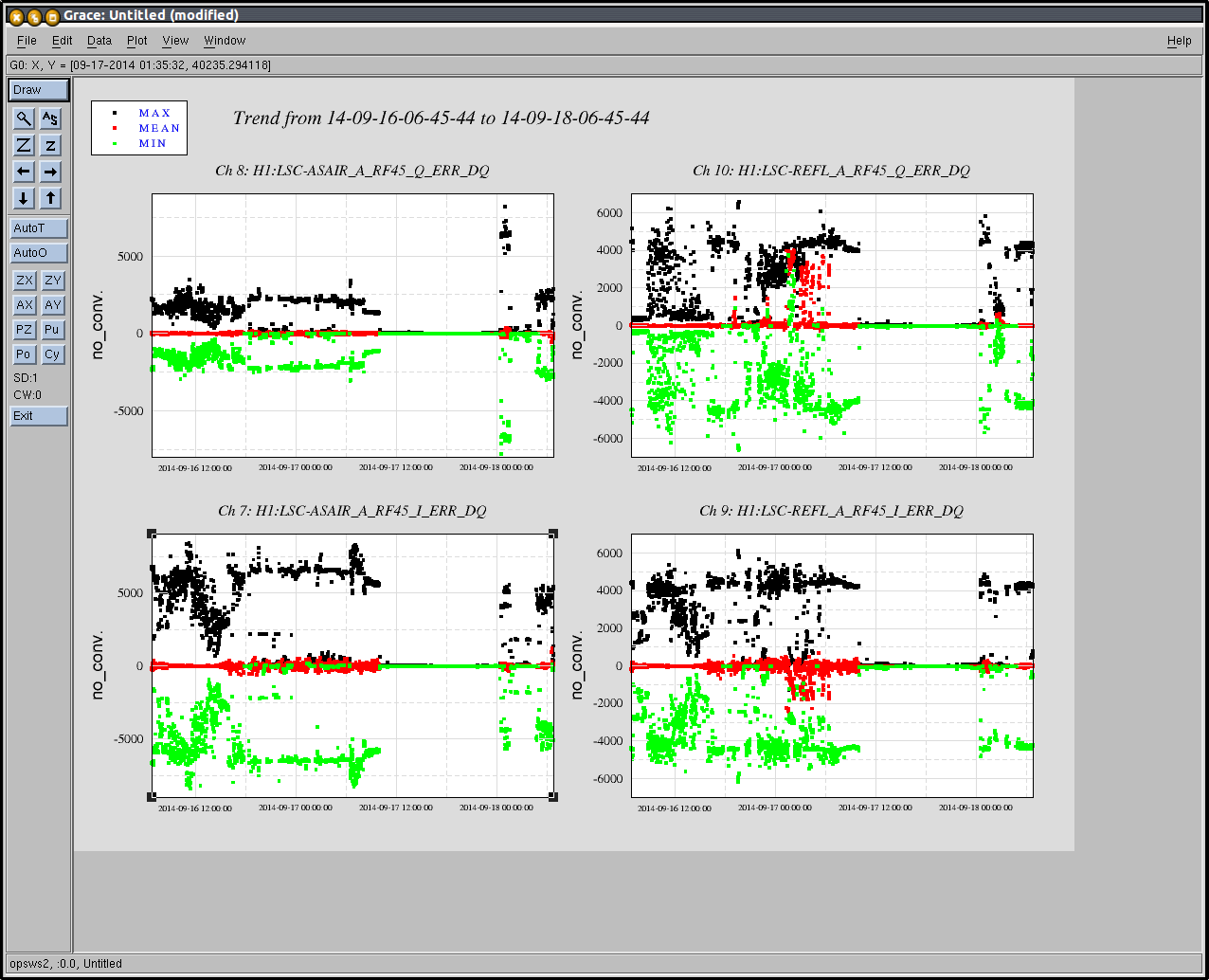
Also, the large fluctuation we saw in REFL_A_RF45 yesterday (alog 13968) was visible today as well before we transitioned to REFL_RF45_Q for MICH. We checked if this behavior is also visible in REFLAIR_A_RF45. This was actually visible in REFLAIR_RF45 as well. This incidicates the fluctuation comes from some kind of common place in the REFL path or the ASAIR_A is imposing this fluctuation in the MICH through its feedback. Once we transitioned onto REFL_A, we saw both REFL_A and REFLAIR RF45 signals suppressed. On the other hand, as expected, ASAIR then started wandering. We should check some clipping or some obvious things on the ASAIR detector tomorrow.
(DRMI lock)
We aligned the SRC by locking SRY with ASAIR_RF45. Also we adjusted the demod phase of ASAIR_B_RF90 such that the signal is maximized in in-phase. At the beginning, we adjusted the demod phase such that the PRMI carrier resonance gave negative values. This was then flipped by 180 deg after we locked the DRMI because this signal stayed at a negative value when the DRMI was locked.
- REFL_A_RF9_I => PRCL
- REFL_A_RF45_Q => MICH
- REFL_A_RF45_I => SRCL
To lock the DRMI, we reduced the MICH gain by a factor of 5 according to Anamaria's DRMI document, but eventually we ended up with a gain reduction of only a factor of three which resulted in repeatable locking. We did not have to change the PRCL gain from the PRMI locking gains as expected. We guessed the SRCL gain from the same document. We fiddled with the control sign and gain for an hour or so and eventually it started locking.
We coarsely adjusted the PRM and SRM M2 stages to maintain the DRMI lock for a long time. The gains are right now based on some models/guesses. So we will revisit these values tomorrrow.
(SRC hopping ?)
We are not sure what is going on, but the SRC seems to jump back and forth between two modes. It looks as if the hopping is triggered by some slow misalignment. Depending on time, it happened as frequent as once per a couple of seconds. And sometimes it did not happen for some time like 20 seconds or so. This is visible in the dark port camera and AISAIR_RF90 which went back and forth between a high and low values. The low value went to a negative number for some reason. We need to investigate this issue more to figure out what is happening.

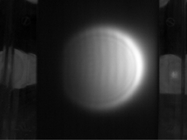

The attached video is of the AS port durring a DRMI lock. Towards the end, there are a few of the mode hopping events that Kiwamu described in his alog.
Also attached is a screen shot of various settings with DRMI locked.
We are setting the intent bit to undisturbed, since as far as we know there aren't any sseismic transfer functions starting tonight and we are leaveing DRMI locked on the sidebands.
When activity starts in the morning, it would be good if the operator could set the intent bit (on the ops screen) to commisioning. This way det char people know when we left the IFO alone
Set intent bit to 'Commissioning' as per Sheila's request.
just for bookkeeping purpose:
the DRMI locking trial was taken place from 5:00-ish to 6:14-ish UTC last night. The first lock was achieved at around 6:14:00 UTC followed by some frequent short locks for 10 minutes. After the first lock there were several good locks.