Lisa, Sheila, Rana, Kiwamu
One of the goals for tonight was to test out the PR3 low frequency oplev servo to see if it improves the long term locking stability. And it helped.
We could keep the carrier PRMI locked for more than 30 minutes which is long enough to perform some studies.
The highest recycling gain we obtained tonight was roughly 15. Still too low. The investigation continues.
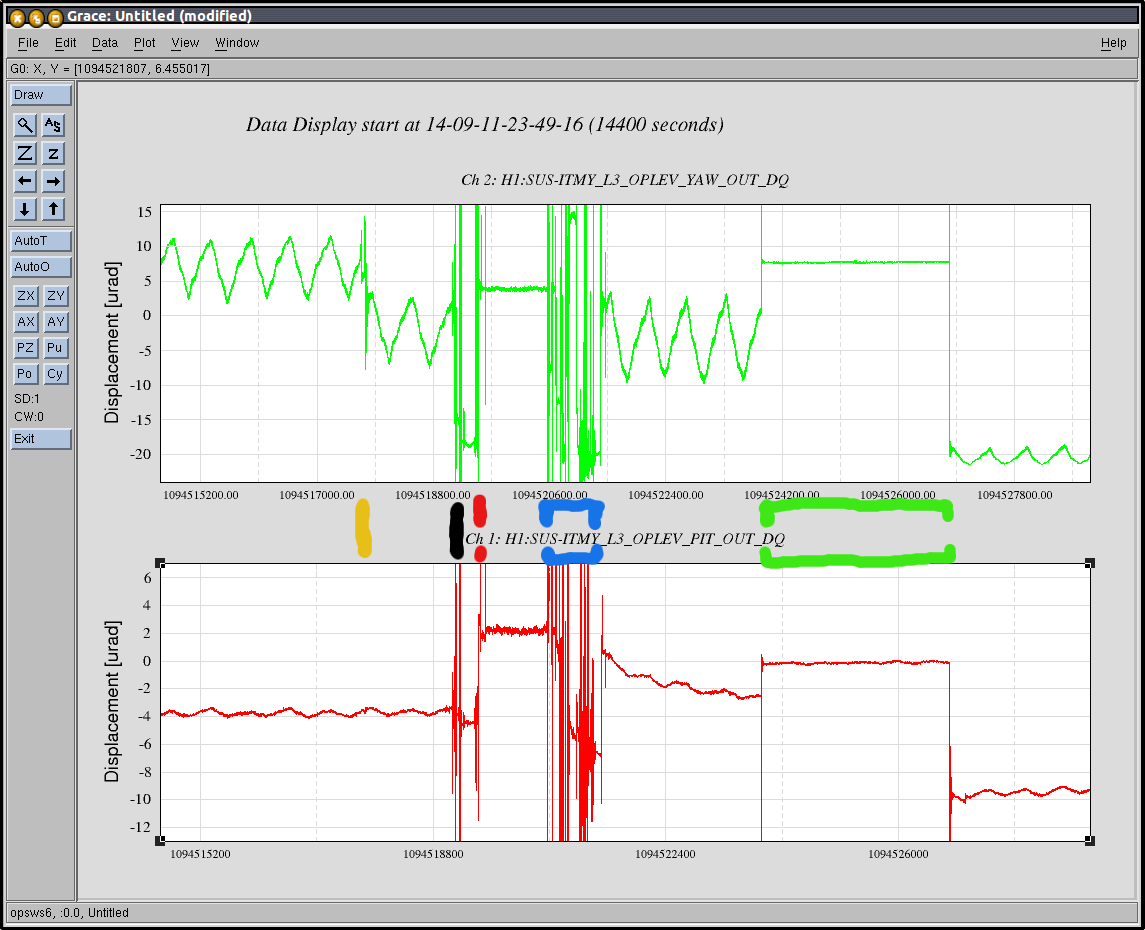
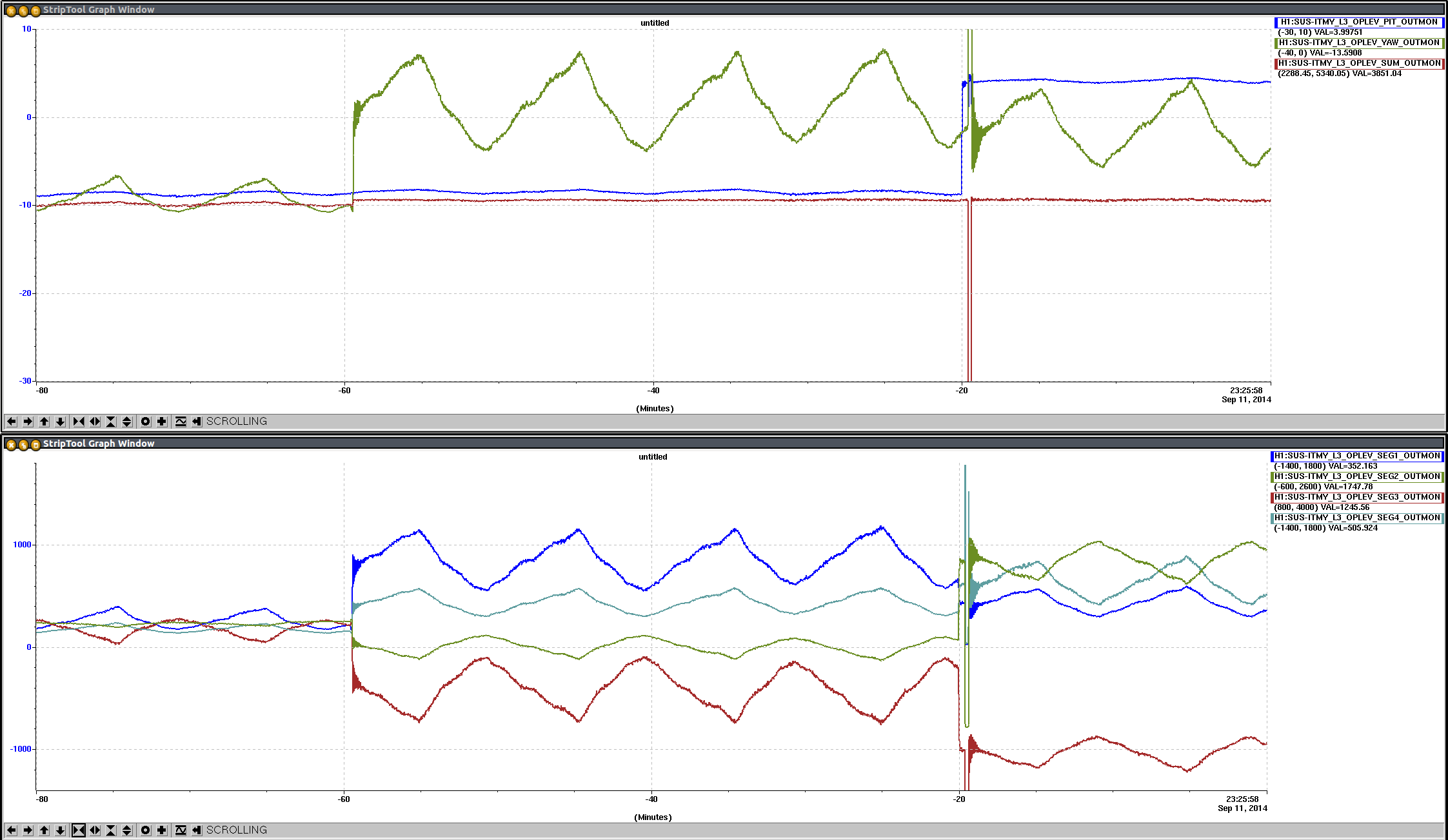
(Angular drift)
The PR3 oplev was engaged all the time during the commissioning tonight. We used the pitch loop and left the yaw loop off all the time. This was good enough to keep the PRMI locked for a long time.
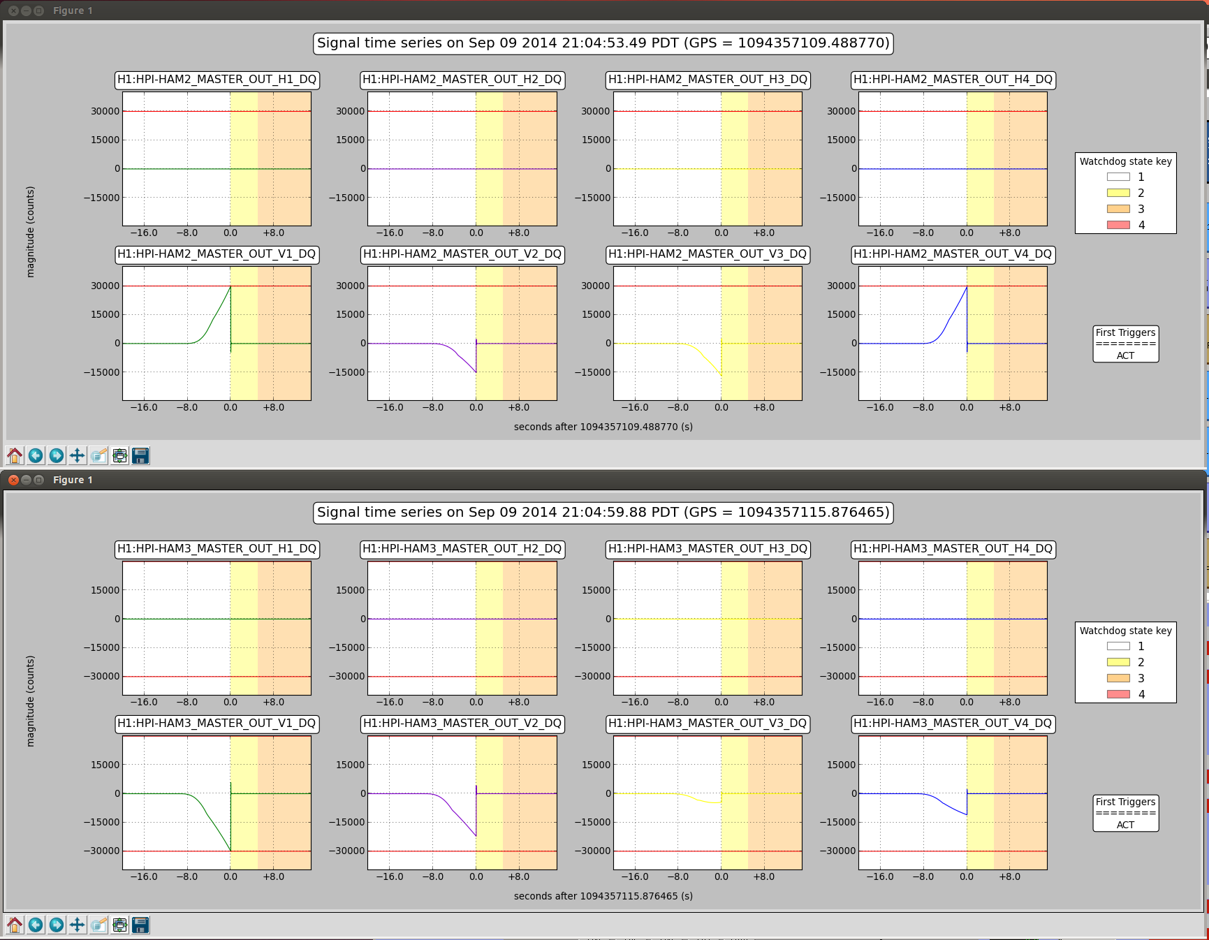
On the other hand, we did not have to pay attention to the BS oplevs -- the BS angular drift is not significant or maybe it is not drifting in the carrier lock condition. Indeed, we did not observe a significant long term degradation in the dark port beam pattern. I attach a vide of the dark port when the carrier PRMI was locked. Note that the BS oplev loops were engaged all time time, which take care of only damping. So there was no control at low frequencies via the opelv.
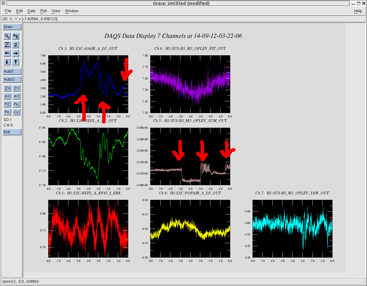
(Some attempt for a better alignment)
The highest build up we obtained tonight was about 3000 counts in POPAIR_A_LF. Compared with the simple MICH configuration, this is 500 times brighter light (it was about 6 counts when a simple MICH was locked with PRM misaligned.) If we ignore a mode-matching effect, this corresponds to a recycling gain of 15.
However, when the intracavity power was maximized, we noticed that the REFL beam had a terrible beam shape -- the prompt reflection from PRM and the leakage fields were far apart. I will post a video of the REFL beam later. So we suspected a large misalignment in IMs.
We then tried moving a combination of IM3 and IM4, and a combination of IM1 and IM4 to see if we can make both the build-up and refl beam better. This was not successful. We could not optimized both at the same time. Tomorrow, we will check out the ABCD matrix for the IMs to make sure we are moving the right degrees of freedom.
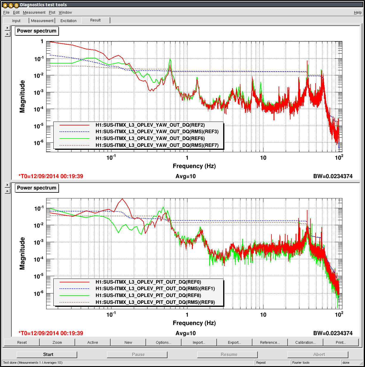
(Some loop studies)
In parallel to the low-recycling-gain study, we measured the open loop of the length loops. The UGF of PRCL was about 40 Hz and MICH was 8 Hz. The phase looked OK. We will quantitatively cross-check the loops with models tomorrow.