We made two additional experiments with the unsuspended, isolated pilot (Corning ETM02) ITMY, in the west bay of the LVEA. (Moreno, Landry)
1) We applied FirstContact to the HR surface, let dry over 24h, measured no excess charge (no more than |3V| at 1" from HR surface, AR surface, and barrel), ripped the FirstContact off the HR face in ~20s *without* doing any TopGun ion gun blowing, and then measured the voltage 1" from the HR surface. We find the resultant charge negative, with a claimed voltage of ~-22kV, -22kV and -22kV at three points across the face of the optic. Assessing the AR surface, we find a voltage 1" from the AR face of -12.1kV, -12.1kV and -11.3kV.
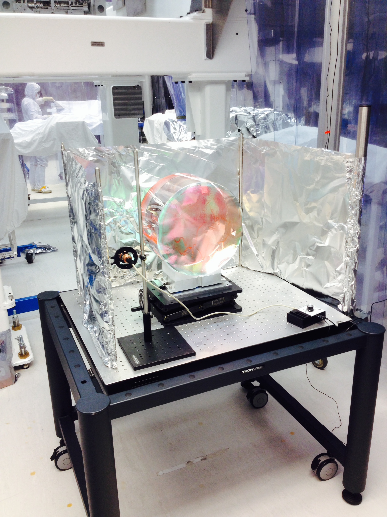
2) We made another trial in which after FirstContacting, we removed the polymer film while TopGun blowing to neutralize the surface. We followed the same basic procedures as outlined in alog 13104, with slightly different timings. The primary change in the experiment was the grounding of the optical table, and the addition of a grounded Al foil shield (see photo attached). The addition of the shield and ground dramatically changed the behaviour seen in the prior experiment linked above: generally, individual measurements that took minutes to settle exponentially to some voltage now settled in seconds. Furthermore, the apparent long time constants for which it seemed necessary to continue with the ion gun (~9min total) were not observed in this experiment. We took 2 minutes to pull the FirstContact, which included a coincident 2 minute TopGun blow, plus one additional minute of TopGun blowing, and measured +18 to +30V at several locations 1" from the surface of the HR side of the optic.
We'll repeat experiment #2 one more time, with shorter intervals between electrometer measurements, to better understand the field sizes, signs, and time constants.
In our final measurement trial of Top Gun de-ionizing of this (FirstContacted) test mass, we used shorter de-ionizing times to understand how quickly charge was being neutralized. Times are impacted by presence of the partial Al shield (in place for this trial).
i) FirstContact was re-applied to the test mass. The test setup was the same as above, and per the photo: grounded table and partial Al foil shield, also grounded.
ii) We then pulled the FirstContact over a period of one-minute, with coincident TopGun de-ionizing.
iii) Measuring the voltage with the field mill 1" from the center of HR surface, we find +440V, and at the limb of the optic (top,right, bottom, left) of +290V, +385V, -12V, and +50V. The sign here is unexpected given prior measurements have shown that post-FC rip, the charge is negative. For the AR surface, we find 0V 1" from the center, and +30V and -20V near the limb.
iv) After an additional 1m of TG de-ionizing, measurements 1" above the HR surface show: +10V (center), +8V, +10V, +12V, +8V (limb top, right, bottom, left). The surface is effectively neutralized. The 1" measurments above the AR surface show +28V (center), 0V (top), +15V (bottom)
v) After an additional 1m of TG de-ionizing (now 3m total), measurements 1" above the HR surface show: +20V (center), +25V, +20V, +15V, +15V (limb top, right, bottom, left). The 1" measurments above the AR surface show +8V (center), +10V (top), +8V (bottom)
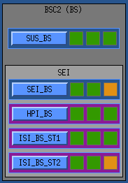
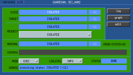 NOMINAL state for HAM managers is "ISOLATED".
 NOMINAL state for BSC managers is "FULLY_ISOLATED" (HPI and both ISIs isolated).
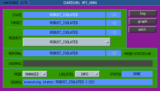 NOMINAL state for HPI is "ROBUST_ISOLATED", for both HAMs and BSCs.
 NOMINAL state for ISI stages is "HIGH_ISOLATED".