Displaying reports 74761-74780 of 76955.Go to page Start 3735 3736 3737 3738 3739 3740 3741 3742 3743 End
Reports until 19:09, Friday 17 February 2012
LHO General
patrick.thomas@LIGO.ORG - posted 19:09, Friday 17 February 2012 (2270)
plots of dust counts
Attached are plots of dust counts > .5 microns. The connection to the dust monitors in the labs was lost for a period of time when one of the wires came unconnected in the MSR. I have attached a plot of H0:PEM-LAB_DST1_MODE to show when.
Non-image files attached to this report
LHO VE
kyle.ryan@LIGO.ORG - posted 16:57, Friday 17 February 2012 - last comment - 13:35, Wednesday 22 February 2012(2268)
Found main leak on YBM
Kyle, Gerardo, John  

Found gross leak on dual 3-pin actuator power feed-through on BSC8 (NW) -> Vented YBM, replaced leaker with one that was bench tested and found not to leak.  As found, in-vacuum cables connectors were not screwed to feed-through connectors -> NOTE: flange-to-flange gap is uniform but conflat joint is not "metal-to-metal".  Seems as if flange bolts are bottomed out in blind holes, tapped holes may be too shallow on this one flange(?) -> Pumping YBM overnight with purge/vent valve "cracked" open.  

  
Comments related to this report
gerardo.moreno@LIGO.ORG - 13:35, Wednesday 22 February 2012 (2282)
Results of inspecting the leaky feedthrough.
It appears that the feedthrough was hit with enough force on the air side to break the weld on the vacuum side.
Photos attached.
Images attached to this comment
LHO VE
kyle.ryan@LIGO.ORG - posted 16:46, Friday 17 February 2012 (2267)
Switched Y-end pumping from Turbo to Ion pump
Kyle, Gerardo 

~0930 hrs. local
H2 SEI
hugh.radkins@LIGO.ORG - posted 16:38, Friday 17 February 2012 (2266)
H2 BSC8 HEPI Offline for fluid line move
We isolated the chamber tubing from the feedline and then shut the pump down.  We drained almost two liters from the system before we decided enough for today.  We'll do some more before moving the lines next week.
We had no real problems except for having a ladder pilfered in the middle of the job.

EricA, HughR
H1 PSL
michael.rodruck@LIGO.ORG - posted 16:19, Friday 17 February 2012 (2265)
H1 PSL installation

AC units have been installed, work on make-up air ducting is in progress. Area for concrete pads for chillers to sit on has been cleared.

Images attached to this report
H2 SUS
jeffrey.garcia@LIGO.ORG - posted 16:07, Friday 17 February 2012 - last comment - 18:36, Friday 17 February 2012(2263)
H2 SUS ITMY M0 & R0 TFs
H2 SUS ITMY 

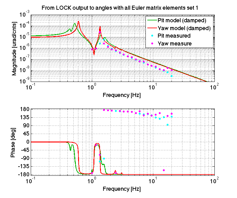
Open loop transfer function measurements were run on the H2 ITMY M0 & R0 top masses last night. The ISI damping loops were closed for the beginning of the measurements. There was a concern as to whether there was rubbing on the earthquake stops for ITMY after  evidence of such on FMY earlier this week.  These measurements show no preliminary signs of rubbing on the ITMY M0 & R0 masses and agree quite well with the models.


Data:
~/SusSVN/sus/trunk/QUAD/H2/ITMY/SAGM0/Data/2012-02-16_1013494514_H2SUSITMY_M0_0p01to50Hz_AllDOFs_tf.mat
~/SusSVN/sus/trunk/QUAD/H2/ITMY/SAGR0/Data/2012-02-17-1013510837_H2SUSITMY_R0_0p01to50Hz_AllDOFs_tf.mat

PDF Plots:
~/SusSVN/sus/trunk/QUAD/H2/ITMY/SAGM0/Results/2012-02-16_H2SUSITMY_M0_ALL_TFs.pdf
~/SusSVN/sus/trunk/QUAD/H2/ITMY/SAGR0/Results/2012-02-17_H2SUSITMY_R0_ALL_TFs.pdf
Non-image files attached to this report
Comments related to this report
jeffrey.garcia@LIGO.ORG - 18:36, Friday 17 February 2012 (2269)
The attached PDF is of the latest ITMY M0 & R0 TFs from the night of 2012-02-16 to the following morning compared with previous measurements of H2 SUS ITMY.   

The pdf has each of the M0 & R0 DoFs plotted with only previous H2 SUS ITMY measurements. Each measurement used the same drive parameters.  

Orange - 2011-11-29 - Monolithic Measurement on LVEA Test Stand, ISI locked.
Black - 2011-12-02 - Floating ISI, Vibration Absorbers ON, L1 & L2 aligned
Magenta - 2012-01-10 - In Chamber BSC8, ISI locked for M0 measurement, ISI UNlocked for R0 meas., No Damping
Cyan - 2012-02-17 - In BSC8, ISI Floating, ISI Damping ON, chamber pump had begun but not completed due to leak

There appears to be obvious indication for rubbing effects on the M0 & R0 top masses.  Every DoF for both masses agree well with the model and are consistent with previous results.

PDFs of Plots:
~/SusSVN/sus/trunk/QUAD/Common/Data/allquads_120217_H2SUSITMY_ALL_TFs.pdf
Non-image files attached to this comment
LHO General
corey.gray@LIGO.ORG - posted 15:59, Friday 17 February 2012 (2264)
Shift Summary
H1 SEI
corey.gray@LIGO.ORG - posted 13:44, Friday 17 February 2012 - last comment - 14:07, Friday 17 February 2012(2260)
Disconnecting BSC8 ISI Cables For Leak Checking

Filiberto will be disconnecting external ISI cables from their respective feedthrus to help Kyle with his leak-checking work of BSC8.  Cables will be re-connected when Kyle gives the ok.

Comments related to this report
filiberto.clara@LIGO.ORG - 14:07, Friday 17 February 2012 (2261)
Associated electronics (ISI Coil Drivers) were powered down.
H2 SEI
vincent.lhuillier@LIGO.ORG - posted 10:58, Friday 17 February 2012 (2258)
Reducing the transfer functions measurements time on the ISIs during phase I and II.

During phase I and II, the ISIs are tested in clean rooms and are subjected to an important airflow disturbance.  Consequently, it is quite difficult to have good quality measurements at high frequencies (100Hz to 1KHz). To improve the quality of the transfer functions, we can split the high frequencies transfer functions measurements into multiple frequency bands but the “quick high frequency transfer functions measurements” become time consuming.

Measurement limitations:
- at HF, the drive is the limit
- at LF, the drive is small and the sensors saturate easily

To reduce the measurement time, we can drive 1 DOF at low frequency and different DOF at high frequency simultaneously. During a test, stage 1 was driven at low frequency while Stage 2 was driven at high frequencies. In the attached plots, there is a comparison when the TFs are measured by exciting one DOF at the time and 2 DOFs simultaneously. It matches. Only, a light difference is observed on the 2 first resonances of the ISI (probablydue to a light change of the plant between the two measurements)

Non-image files attached to this report
H2 SEI
vincent.lhuillier@LIGO.ORG - posted 10:50, Friday 17 February 2012 (2257)
HEPI transfer functions

HEPI transfer functions
The first set of transfer functions was measured on BSC8 from 2mHz to 500Hz. The 700mHz-10Hz frequency band was measured in 2 configurations:
- ISI undamped (2012_02_15)
- ISI damped (2012_02_16)

The HEPI transfer functions can be seen at:

https://svn.ligo.caltech.edu/svn/seismic/HEPI/H2/ITMY/Data/Figures/Transfer_Functions/Measurements/Undamped/

-          LHO_HEPI_BSC8_TF_L2L_Raw_from_ACT_to_IPS_2012_02_16.fig

-          LHO_HEPI_BSC8_TF_L2L_Raw_from_ACT_to_IPS_2012_02_16.pdf

-          LHO_HEPI_BSC8_TF_L2L_Raw_from_ACT_to_L4C_2012_02_16.fig

-          LHO_HEPI_BSC8_TF_L2L_Raw_from_ACT_to_L4C_2012_02_16.pdf


The ISI damping loops are effective between 1Hz and 8Hz. The effect on HEPI transfer functions is limited but visible on the 1.25Hz and 5 Hz resonances. A comparison between the two configuration can be found at:

https://svn.ligo.caltech.edu/svn/seismic/HEPI/H2/ITMY/Data/Figures/Transfer_Functions/Comparisons/L2L/

-          LHO_ISI_BSC8_Comparison_TF_L2L_ACT_H_to_L4C_H_20120215_vs_20120216.fig

-          LHO_ISI_BSC8_Comparison_TF_L2L_ACT_H_to_L4C_H_20120215_vs_20120216.pdf

-          LHO_ISI_BSC8_Comparison_TF_L2L_ACT_V_to_L4C_V_20120215_vs_20120216.fig

-          LHO_ISI_BSC8_Comparison_TF_L2L_ACT_V_to_L4C_V_20120215_vs_20120216.pdf

If you look carefully, you can see light bumps at the junctions between the different sections (10mHz for instance) of the transfer functions. To evaluate the non linearity, I drove a sine wave at 200mHz and 4Hz using different amplitudes (100cts, 300cts, 1000cts, 3000cts, 5000cts) (attachment).

Non-image files attached to this report
H2 SEI
vincent.lhuillier@LIGO.ORG - posted 10:40, Friday 17 February 2012 (2256)
L4C gain on the HEPI pier interface D080521

Low gain on the HEPI pier interface D080521
It is quite surprising to see that the HEPI L4C signals don’t overshoot +/-100 counts on the ADC (attachment 1) when the actuators are not driven.  After checking that all elements of the readout chain were turned on, we measured the L4C gain of one HEPI pier interface D080521. The gain is 22 and a 0.1V input offset gives 3600counts on the ADC as expected.
After comparing calibrated spectra of the HEPI L4Cs (on top of the piers) with spectra of the ISI L4Cs (stage 1), the HEPI L4Cs spectra don’t look wrong.
L4C gain in D080521 seems low.

Non-image files attached to this report
H2 CDS
james.batch@LIGO.ORG - posted 10:39, Friday 17 February 2012 (2255)
Default NDS server assignment changed
The default NDS server assignment that is made for new shells has been changed to use h2nds0 instead of h2nds1.  This will affect any program or shell started after 10:38 AM PST on Feb. 17, 2012.
LHO General
patrick.thomas@LIGO.ORG - posted 08:25, Friday 17 February 2012 (2254)
plots of dust counts
Attached are plots of dust counts > .5 microns for February 15 and 16.
Non-image files attached to this report
LHO VE
kyle.ryan@LIGO.ORG - posted 17:37, Thursday 16 February 2012 (2252)
Big gas load in YBM
Kyle, Gerardo, John

Had valved-out QDP80 pump from YBM before leaving last night.  YBM pressure was 20 torr at that time.  Pressure rose to 200 torr in ~18 hours, i.e. large unexplained gas load in YBM volume -> Resumed pumping YBM with QDP80 this morning.  Pumped adjacent annulus volumes (BSC8, GV1 and GV3-GV5 already under vacuum).  Connected leak detector in parallel with QDP80 pump path and set detector up for high pressure leak testing (10 torr max inlet pressure).  Once YBM pressure reached 10 torr, Gerardo and I did a "rehearsal" exercise by spraying some feed-throughs on BSC8 -> Noticed a large delayed response after tens of seconds.  Time constant believed to be around 1800 seconds for these conditions.  Signal continued to rise for ~30 minutes after initial (10 sec/flange dwells) until signal "railed" the leak detector at 9.9 x 10⁻⁴ torr*L/sec. -> Surprisingly, Gerardo was unable to find this "wopper" leak by utilizing the stethoscope!  We probably could hear this leak with our unaided ear if there wasn't so much background noise in the LVEA. -> For tonight, I am leaving the YBM vent/purge valve "cracked" open a little so as to keep a viscous stream flowing in the correct direction in the event of a QDP80 stoppage during the night.  This way we won't have to valve-out the pump overnight and we can resume leak testing in the morning without having to wait "hours" to get back to 10 torr.
H2 PSL
michael.rodruck@LIGO.ORG - posted 17:20, Thursday 16 February 2012 - last comment - 13:19, Friday 17 February 2012(2251)
PSL shut off overnight

PSL is shut off for the night to allow Robert S. to make accelerometer measurements on the periscope, without interference from the chilled water lines. PMC, ISS, FSS servos are off, everything will be started back up tomorrow morning.

HEPA units are off, make up air is set to 30%, creating a ~0.01" water pressure differential between laser and anteroom. AC units were shut off via touchpad interface, but they may still be on.

Comments related to this report
michael.rodruck@LIGO.ORG - 13:19, Friday 17 February 2012 (2259)

Laser is back up

H2 AOS
keita.kawabe@LIGO.ORG - posted 16:40, Thursday 16 February 2012 - last comment - 18:01, Thursday 16 February 2012(2248)
TMS is hung

Today we installed the fall protection wire and temporary vertical protection bars for the TMS isc table, and removed the Genie, while the cube is still on EQ stops. It went fine.

Originally the temporary protection bars weren't required at this stage, however the new initial alignment procedure the TMS and the intial alignment people have been working on requires that a large target is mounted on the input aperture of the telescope plate. Since this totally changes the balance of the TMS/tele, we needed temporary EQ stops on the vertical protection bars.

Comments related to this report
daniel.hoak@LIGO.ORG - 16:56, Thursday 16 February 2012 (2249)
Photo 1:  It was difficult to attach our preferred cable into the bottom QPD bracket on the transmon table. (This is for the green QPDs, we think.) We removed the unconnected pins but this didn't help; in the end we switched the cables and things worked ok. (We preferred to use the cable with more slack for the lower connection, but c'est la guerre.) 

Now, the cable arrangement is (photos 2-5): 

Top QPD connector (red QPDs): S1104109
Bottom QPD connector (green QPDs): S1104468

Top ETM-side connector (picomotors): S1104116 
Bottom ETM-side connector (IR beam diverter): S1104114 

These numbers don't matter much in the long run, other than we will take care to plug the other end of the cables into the proper ISC connector on the bracket on the ISI table. (And then check that the ISC cables are connected to the dummy feed-through in the proper way...et cetera, et cetera.) 

Other attached photos: the transmon table is now hanging on its own. Note that since the telescope mirrors are silvered, if you look down the axis of the telescope you can see reflections all the way up to the periscope mirrors. Also, if you look down the green path from the in-air side, you can faintly see a QPD at the other end!
Images attached to this comment
keita.kawabe@LIGO.ORG - 16:53, Thursday 16 February 2012 (2250)

We were hit by Tycor DB25 connector again.

In general,  female pins are not centered in the hole (it's pretty much dependent on the tension of the cables that are attached to the pins inside), and quite often we have minor interference between male and female pin. When this happens, if we force it the pins could be broken.

Today, one of the QPD male connectors didn't want to mate with female one, and one of the male connector pins was somewhat marred by the female pin. To ease things up, I unbent the male pins so it aligns better with the female pins, which didn't help, and then removed all unused pins, which didn't help. Finally I swapped the cables with male pins (basically swapped green and red QPD cables connecting the table and the ISI), and that did the trick.

See the picture of the disassembled connector with unused pin removed. You can see that the 6-th pin from the right top has a scar.

keita.kawabe@LIGO.ORG - 18:01, Thursday 16 February 2012 (2253)

We still need to continue cable business, then back off all EQ stops to fully suspend it, then look at the BOSEM signals.

We might be able to have a look at the position of the telescope entrance aperture in the afternoon.

H2 SEI
hugo.paris@LIGO.ORG - posted 15:50, Thursday 16 February 2012 - last comment - 15:13, Friday 17 February 2012(2245)
BSC 6, gaps under the root of small blades

Jim, Hugo

Issue
LLO have a BSC-ISI that is under-loaded by 400lbs. They noticed that its small blades where lifted from their clamp-plates. They measured this gap by inserting shims at the blade/clamp-plate junction. A 1.5 mils-thick shim could be inserted by approximately 18/64” in the whole length of that junction.

Test:
We did the same test here at LHO on BSC6, which is reasonably loaded, in order to help LLO diagnose. The access was limited. Only two blades were tested. They could only be tested along 2” of the junction’s length.

Result:
Observations are the same for both of the blades that were tested. A 1 mil-thick shim could be inserted by approximately 28/64”, and a 2 mils thick shim could be inserted by approximately 19/64”.

Conclusion
The gaps measured on LHO-BSC6 are similar to the ones measured on the unit studied at LLO. Hence, the space measured between the blades and their clamp-plates doesn’t seem to be a justification for a BSC-ISI to be under-loaded. 

Suggestion:
Further discussion revealed that our bolts were lubricated before torqueing. Lubrication allows reaching a higher level of compression before tripping the torque wrench. It also revealed that our bolts were torqued to a higher torque value. 

Comments related to this report
hugo.paris@LIGO.ORG - 16:23, Thursday 16 February 2012 (2247)

Higher torque allowed LLO to increase their mass budget

As the shim test performed did not appear to be impacted by the torque difference, it might be interresting to see if torque impacts the value of the thickest shim that can be inserted in that gap.

hugo.paris@LIGO.ORG - 15:13, Friday 17 February 2012 (2262)

Jim, Hugo,

Gaps were re-measured today. The measurement consisted in trying to insert the thickest shim possibe in the blade/clamp-plate junction. We were able to insert a 5mils shim while LLO managed to insert a 6.5mils shim before re-torquing their blades.

The effect of torque seems more noticable at the edge of the blade/clamp-plate junction.

Displaying reports 74761-74780 of 76955.Go to page Start 3735 3736 3737 3738 3739 3740 3741 3742 3743 End