This is to get a good reference for the corner station alignment.
Prcedure:
Align TMSX, then ITMX, then ETMX, using arm baffle PDs.
Then steer PR3 to get the green transmission in ISCT1.
Then align IR light using PR2 and IM4/IM3 to the arm.
Results:
Green beam locked to the arm, and the green beam was steered to the right location in ISCT1 using PR3.
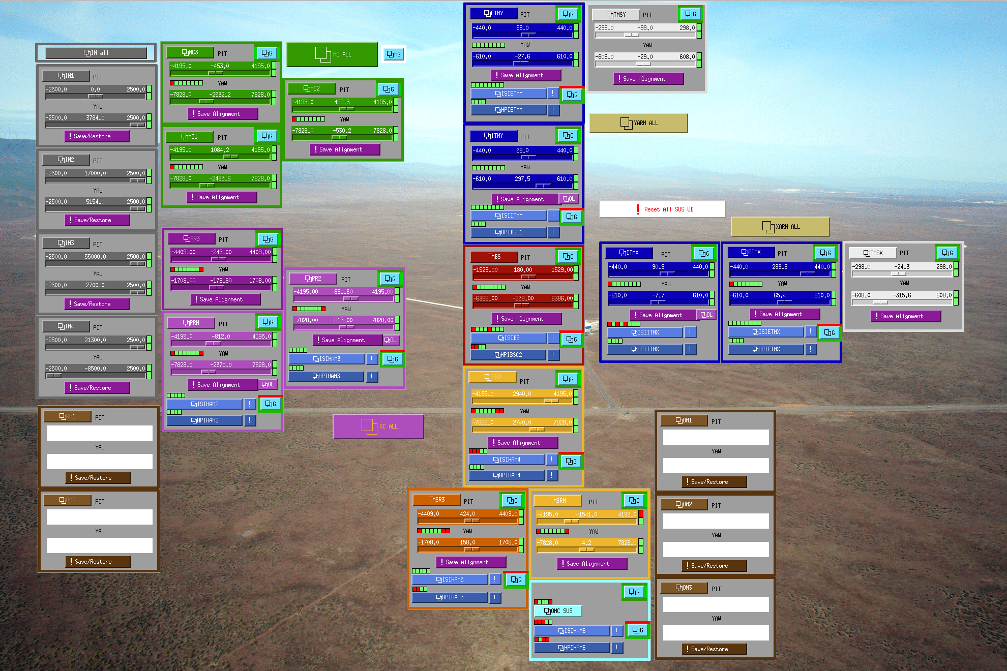
Good alignment slider values are:
|
|
PIT |
YAW |
|
TMSX |
-24.25 |
-315.55 |
|
ETMX |
289.9 |
65.4 |
|
ITMX |
90.9 |
-7.7 |
|
PR3 |
-245.0 |
-178.9 |
|
PR2 |
682.6 |
615.0 |
|
IM4 |
21400 |
-8500 |
PR3 slider offset used to be (P,Y)=(-279, -80) until this morning, now it's (-245, -178.9), the difference is (34, -98.9) urad.
Due to ITMX motion, the ITMX number might be off by a few urad, and the errors in PR3, PR2 and IM4 should follow ITMX via some ABCD matrix.