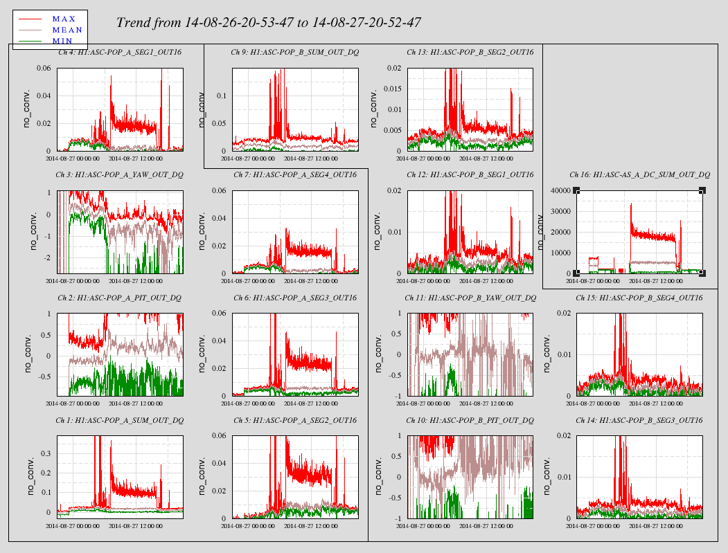
Summary
- OM1/2/3 showed huge angle to angle off-diagonal coupling of the order of 100% during the commissioning last week.
- Yesterday I figured out that the reason was incorrectly and sneakily set non-identity DRIVEALIGN matrix.
- Once DRIVEALIGN was fixed, I could measure the Pitch-to-Yaw (P2Y) and Yaw-to-Pitch (Y2P) couplings.
They were about 30% and 10%, respectively.
- A small arithmetic calculation revealed that these P2Y and Y2P can't be elliminated by the four coil gains.
Namely we need different coil balance for elliminating P2Y and Y2P independently.
- This has been done by adjusting the offdiagonal elements of DRIVEALIGN. As a result the P2Y and Y2P have been reduced
smaller than ~3%, even though the decoupling matrix (DRIVEALIGN) so far is a frequency independent one.
- One question: Why do we have the decoupling matrix only in the ISC signal chain on the every suspension?
This way, we can't enjoy the benefit of diagonalization for the other actuation signals such as alignment offsets,
damping servo outputs, test inputs. Is there a philosophie behind the current design?
Details
1. DRIVEALIGN
It turned out that the all elements of the DRIVEALIGN matrix (3x3) were the unity. Alas! This meant that any input (L, P, or Y) result in
the same actuation. This was overlooked because the matrix button still indicated only the diagonal elements were active (green)
even though that was not true. The warning in the DRIVEALIGN screen tell (in a very dark texts), the indicator criteria is different
between the diagonal and off-diagonal elements. It saids FM1 needs to be turned on to turn on the green indicator for the off-diagonal
elements. This is confusing as the frequency independent element in the off-diagonal element does not trigger the indicator. I strongly
feel that we should use the same criteria for the off-diagonals as the one for the diagonal elements.
For now, FM1 of the P2Y and Y2P elements have dummy k=1 filters so that we can activate the indicators.
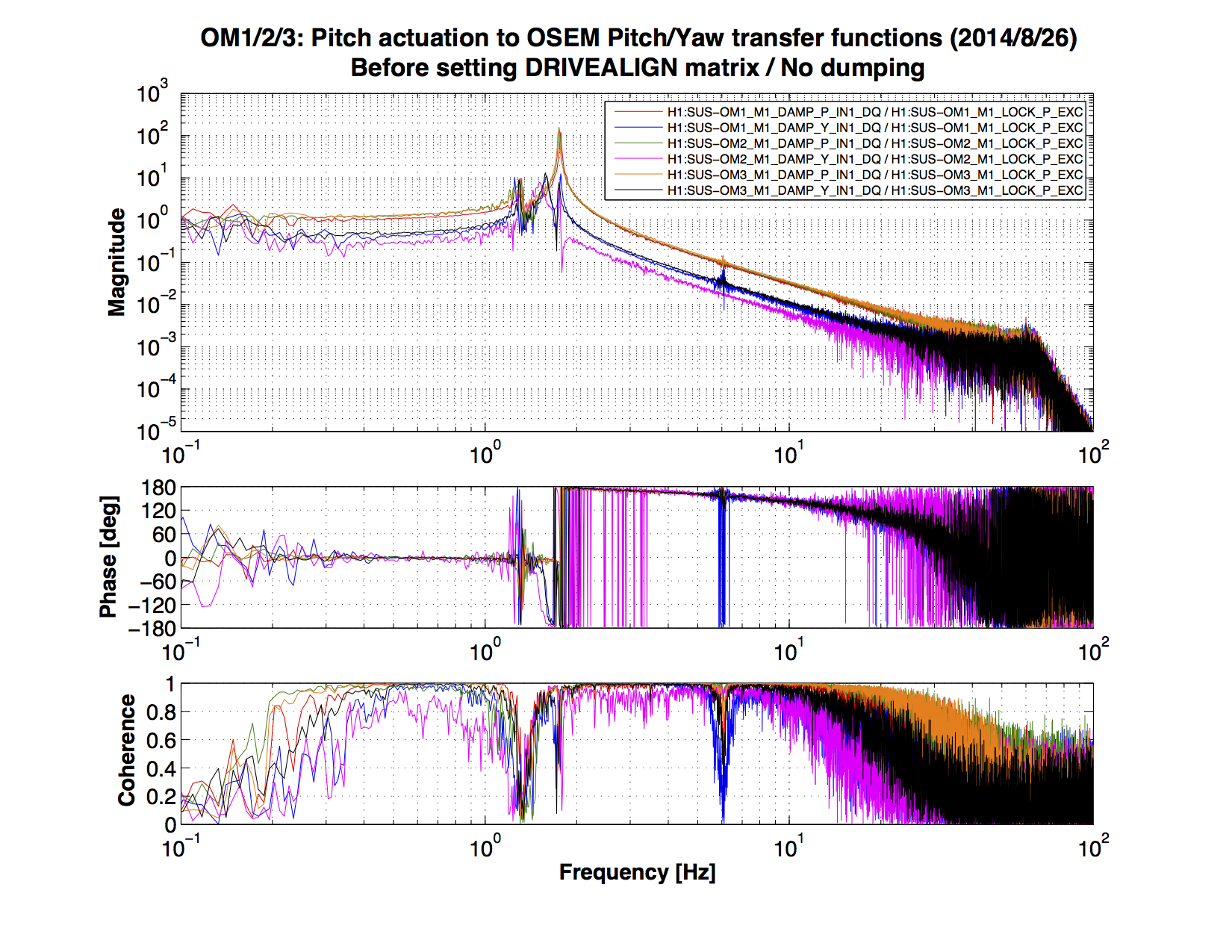
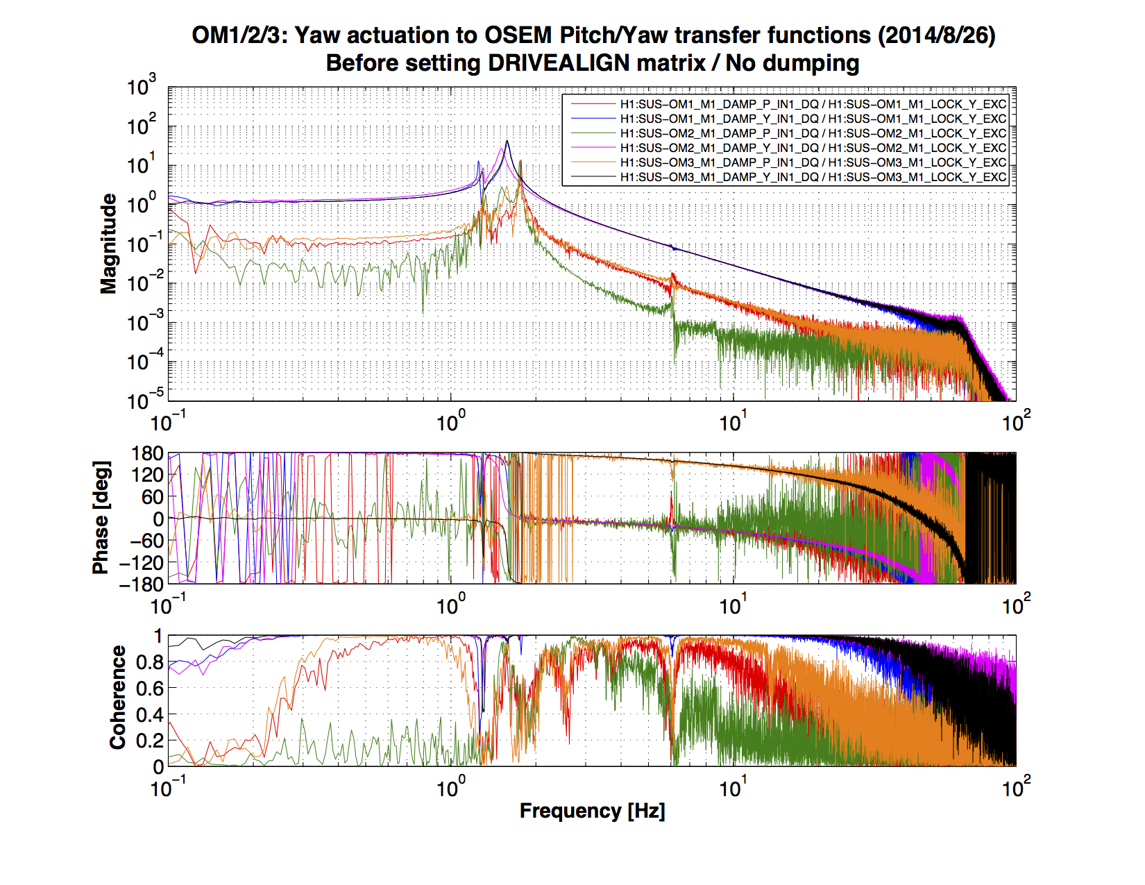
2. P2Y/Y2P coupling measurements
Once the DRIVEALIGN was modified to be an identity matrix, more reasonable angle-to-angle coupling started to show up in the measurements.
The measurements have been done with no damping in order to avoid confusion caused by the coupling coming from the damping loop.
140826_TT_P2A and 140826_TT_Y2A show the measured transfer functions from the Pitch or Yaw excitations to the Pitch and Yaw local readings.
As I did not have the beam, the OMC QPD signals were not used. The coupling ratios (P2Y/P2P or Y2P/Y2Y) were picked up at 0.5Hz and 5Hz.
P2Y is ranging from 0.18 to 0.39 while Y2P is from ~0 to 0.13. They are summarized in the following table
|
|
| |
P2Y@0.5Hz |
P2Y@5Hz |
| |
Y2P@0.5Hz |
Y2P@5Hz |
|
OM1 |
| |
0.394 |
0.326 |
| |
0.088 |
0.100 |
|
OM2 |
| |
0.236 |
0.176 |
| |
-0.015 |
0.014 |
|
OM3 |
| |
0.369 |
0.313 |
| |
0.109 |
0.126 |
The OM2 Y2P coupling is basically such small that the measurement crossed the zero due to noise and had unstable sign.
For the decoupling calculation, the average of the LF (0.5Hz) and HF (5Hz) numbers were used.
3. Coil balance is incapable for P2Y/Y2P decoupling
Suppose we have perfect coil balance. The pitch and yaw actuations (P and Y below) are distributed to each coil equally (the middle matrix).
The actuation forces are recombined at the suspension (the left most matrix below). This reproduces pure pitch and yaw motions (the right most P&Y)

Now we have the actuator response modified by alpha, beta, gamma, delta.

As you can see, the decoupling terms come in symmetrically. We can't decouple P2Y and Y2P independently by the coil balance.
Note that this is obviously not true for A2L, L2A couplings.
4. Decoupling by DRIVEALIGN
For the above reason the DRIVEALIGN matrix was used for the decoupling. This was easy to implement as we just plug in
the inverse matices of the 2x2 coupling matrix. The below is the matrix plugged in.
|
OM1 |
Lin |
Pin |
Yin |
|
Lout |
1 |
0 |
0 |
|
Pout |
0 |
1.0352 |
-0.0976 |
|
Yout |
0 |
-0.373 |
1.0352 |
|
OM2 |
Lin |
Pin |
Yin |
|
Lout |
1 |
0 |
0 |
|
Pout |
0 |
1 |
0 |
|
Yout |
0 |
-0.206 |
1 |
|
OM3 |
Lin |
Pin |
Yin |
|
Lout |
1 |
0 |
0 |
|
Pout |
0 |
1.0419 |
-0.123 |
|
Yout |
0 |
-0.356 |
1.0419 |
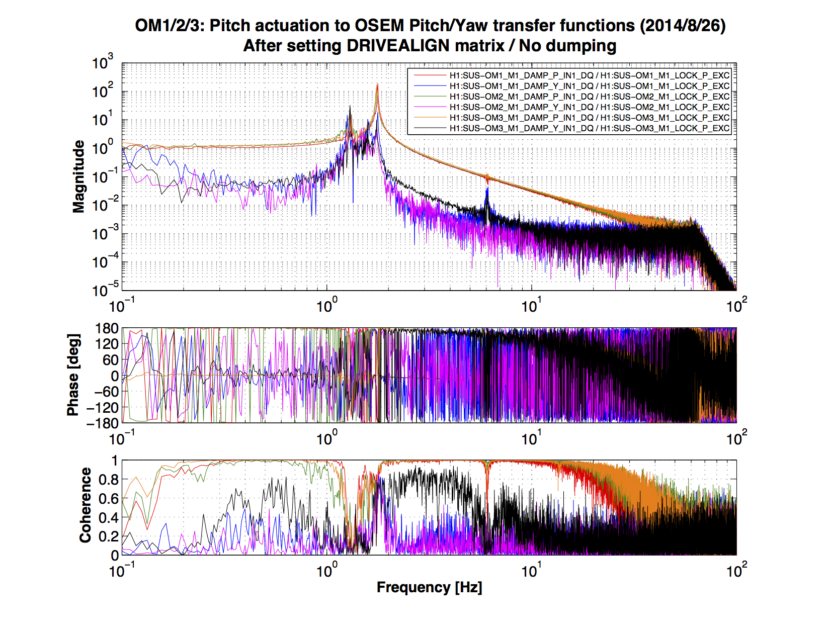
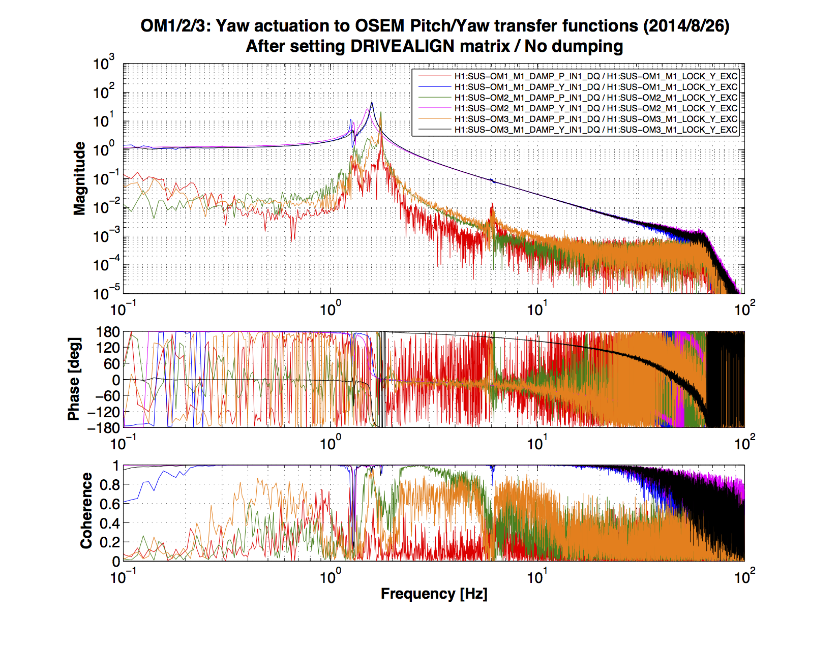
5. Resulting improvement of the coupling
After the new DRIVEALIGN matrices were plugged in,the same measurements wererun. The result for Pitch and Yaw excitations are found
in 140826_TT_P2A_after.png and 140826_TT_Y2A_after.png. The coupling is reduced to ~0.03 or better. This is enough for the further
work on the alignment servo.
If the further decoupling we should install a frequency dependent decoupling.
6. Decoupling topology
But a question arose:
In this topology, only the ISC signals enjoy the benefit of the decoupling.
The alignment offsets (i.e. the alignment sliders), test inputs, and damping actuations do not go through the decoupling matrix.?
Is this what we want? Don't we want to have a DRIVEALIGN FM matrix after the summing node before the euler-to-osem matrix?
Of course, we can convolve the decoupling into the euler-to-osem matrix, in principle, but I don't want to mess up that matrix.

