J. Kissel, T. MacDonald

While waiting for the CDS system to be restored after the scheduled power outage, and for B&K to release licenses, Tim and I spent some quality time with a 3 [lb] sledge hammer, a GS13, some concrete, and SR785. We found a large (~45x12 [sq.ft]) area of empty open LVEA floor (don't tell Jodi!), set up a GS13 in the middle, and used a B&K hammer to hit 10 locations along an 40 [ft] line, each separated by 5 [ft]. Sadly, I think the result is null, but still -- null results can be interesting results. If one squints their eyes, one might be able to claim some coherence with a feature between 5-10 [Hz], but we would need more data to determine if anything in this measurement real slab dynamics. Plots attached, details below.

Details
-------
Timeline
- Hooked up S13 and Hammer to SR785
- Tried several binwidths and frequency ranges, looking for interesting features
- Didn't get any consistent coherence; looked at spectra of S13; decided its spectra looked too featureless and time series didn't look too promising
- Grabbed GS13s 568V and 574V, some power supplies, and freshly made power cable
- After some struggles with a wonky power supply, confirmed that both GS13s 568V and 574V are fully functional (looking at time series alone) with different power supplies
- Hooked up GS13 to SR785, with hammer
- Played with bandwidths and frequency ranges again (went as low as 62 [mHz]), settled on 1 [Hz] binwidth, from 1-400 [Hz], with 10 avgs. We justified the range with "the sledge wouldn't be able to move enough mass to excite anything lower than 1 [Hz], and we're already getting crap coherence, might as well make the measurements quick."

Cable construction:
- Used D0902011 to determine pinout of signals coming out of GS13 military connector. The GS13 needs +/- 15 [V] on pins D and F, respectively with pin R as GND. The +/- legs of the differential GS13 signal are on K and L, respectively.
- Followed signals through Signal / Power pigtail breakout cable that came already attached to the GS13. D to pin 1, F to 3, and R is connected to both 2 and 4. The + GS13 signal is connected to the inner coax of the BSC, and - to the sheild (*tsk*tsk*). See attached pictures for connector pinouts of mil and power connections.
- Aaron/Richard fabricated a power-to-banana cable. (+15 [V]) 1 to Red, (GND) 2 to Green, (-15 [V]) 3 to White, (GND) 4 to Black, though the banana ends of both Green and Black are Black.

Calibration of TF:
- B&K Hammer:
   - gain = 0.2356 [mV/N] (from calibration datasheet)
   - assumed frequency independent
- GS13:
   - 2200 [V/(m/s)] (from eLIGO knowledge, confirmed by a few web sources)
   - assumed frequency independent, since instrument response is flat above 1 [Hz] natural frequency of the instrument
   - D050358 preamp gain of (1+R2/R1)*(1+R4/R5) = 40.2 [Vout/Vin]
   - Integrated once (divided by 2*pi*freq) to get displacement units
   - Divide by 2 for only reading in one leg of differential signal

Data and analysis script live in
${SeiSVN}/seismic/Common/Data/2014-08-14_LHOLVEASlabCharacterization/


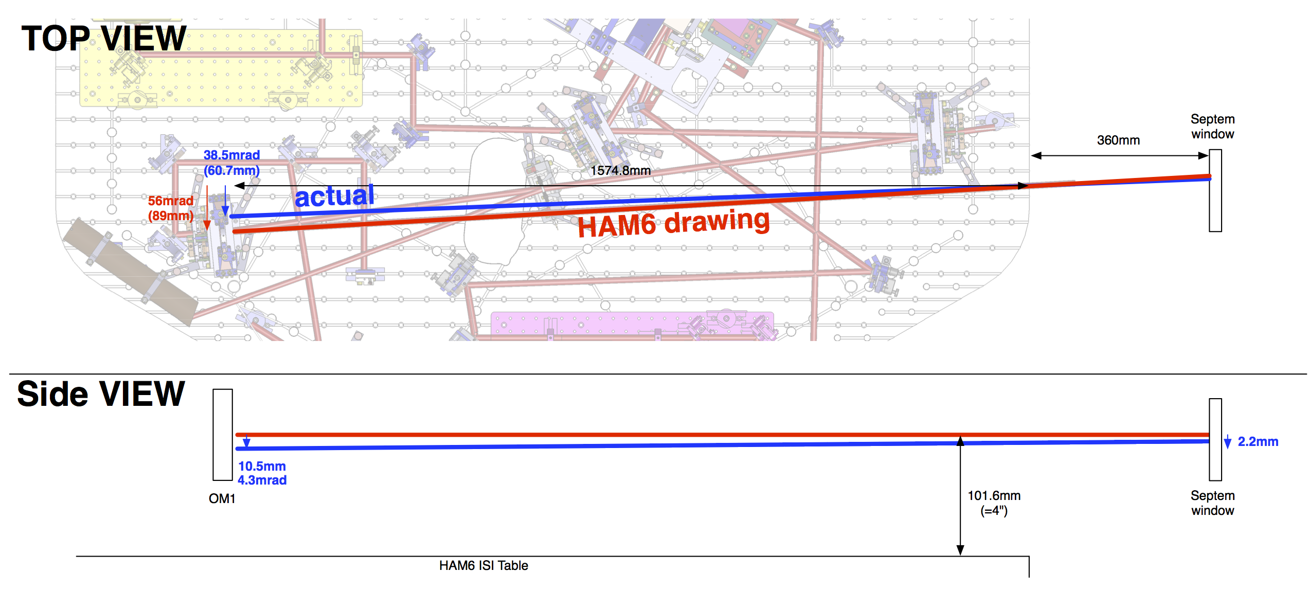
The photo of the septum window attached