rich.abbott@LIGO.ORG - posted 22:04, Sunday 20 July 2014 - last comment - 22:10, Sunday 20 July 2014(12881)
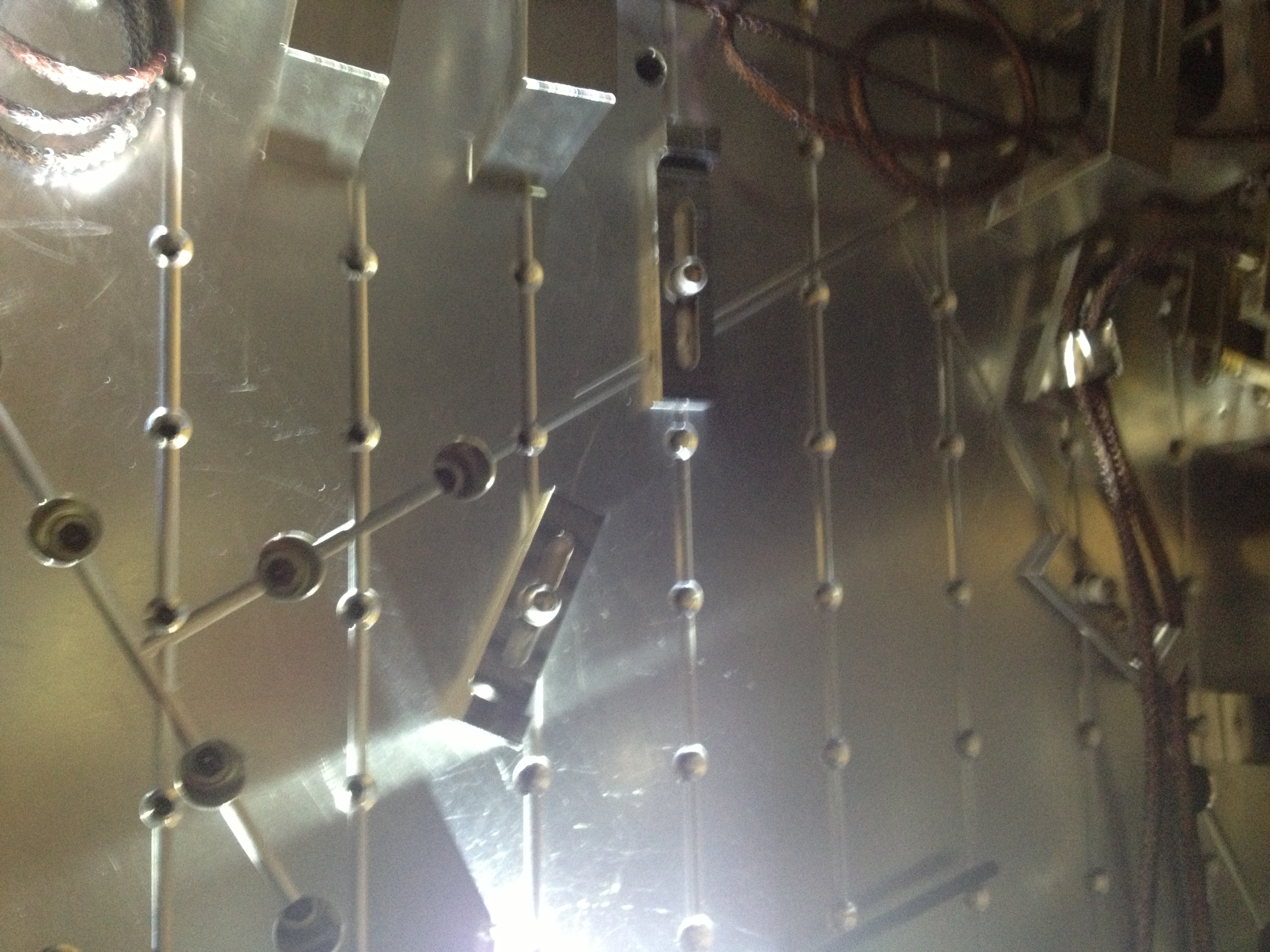
Picomotor Washers, ISS Array HAM2
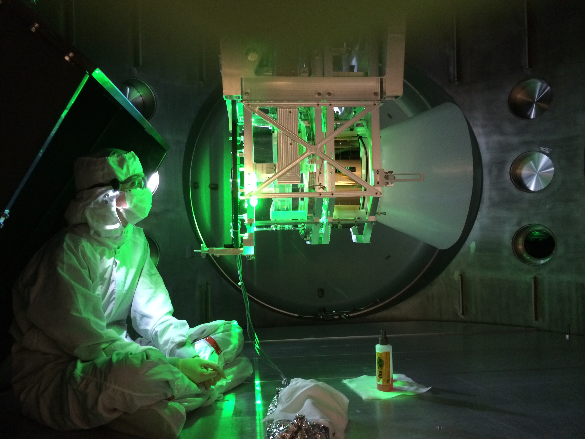
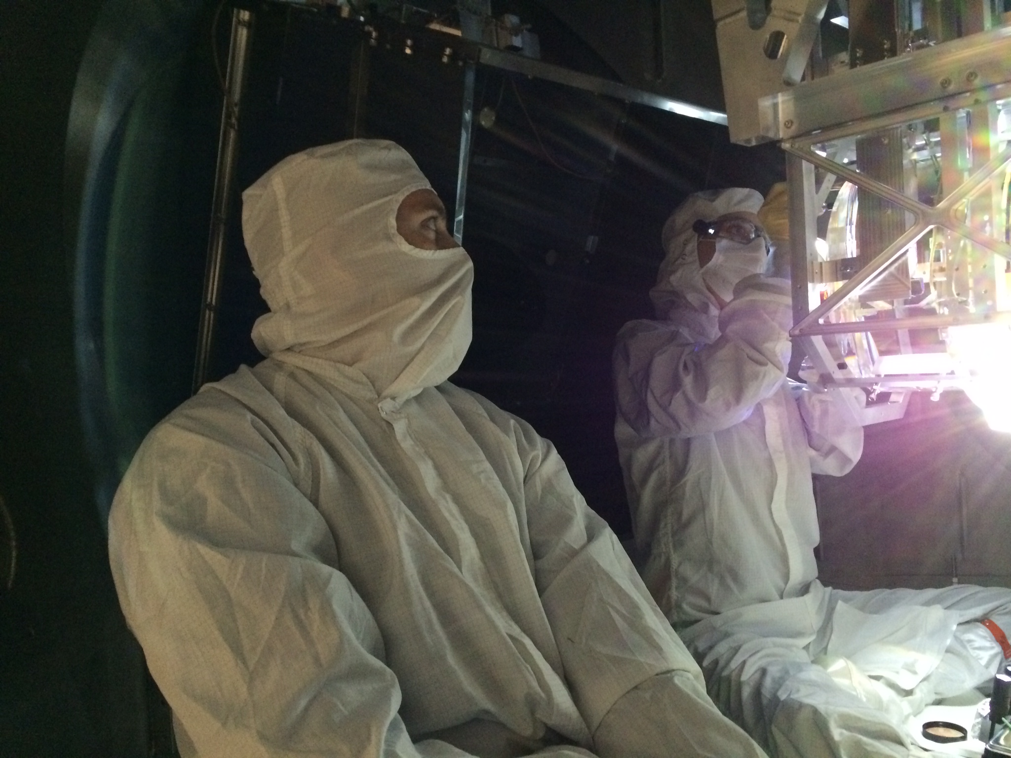
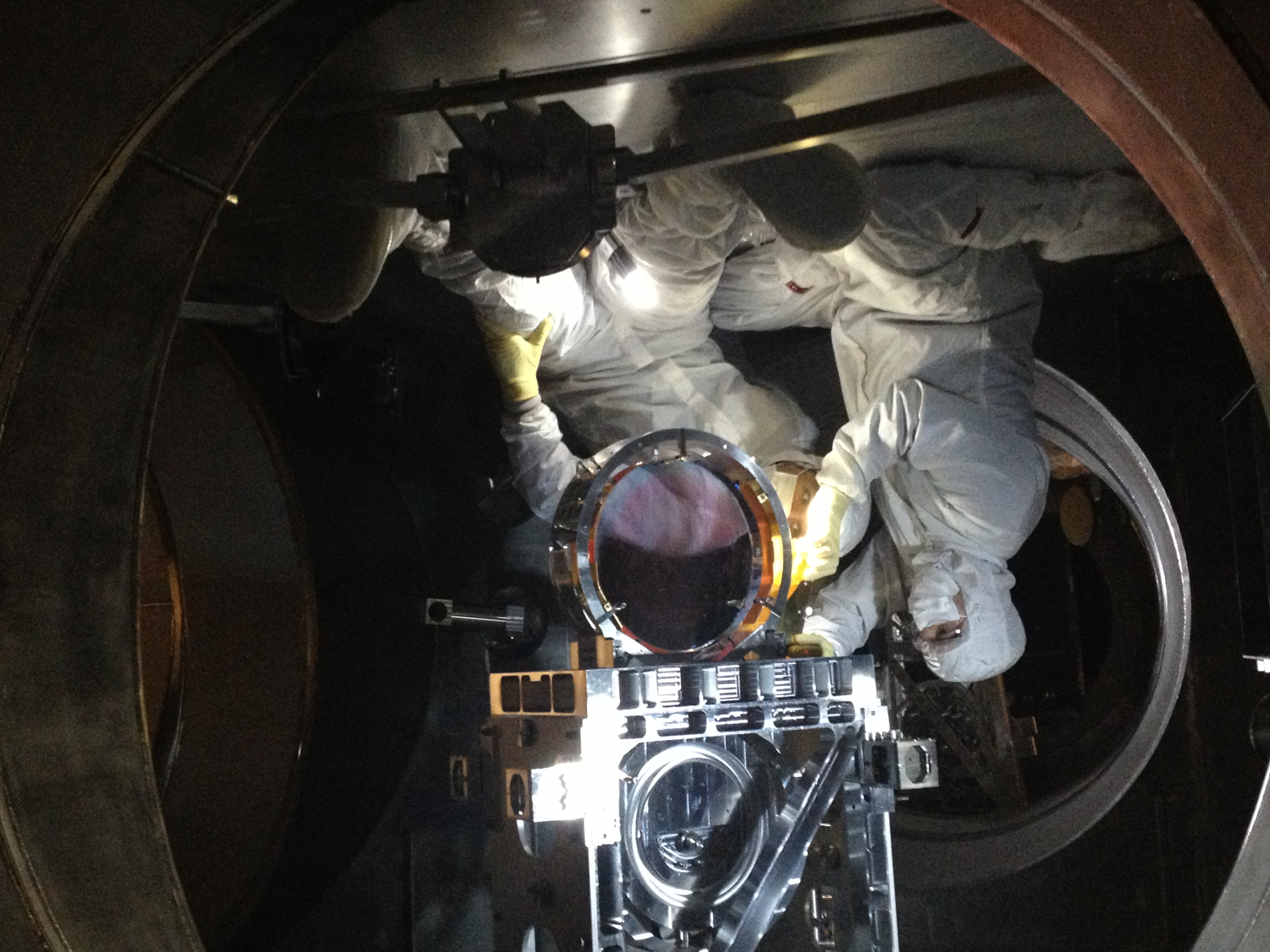
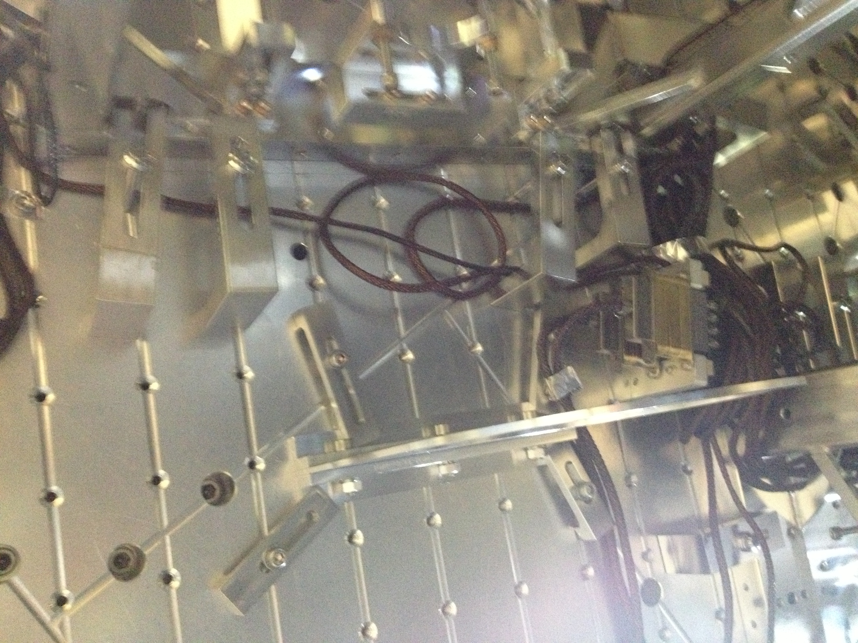
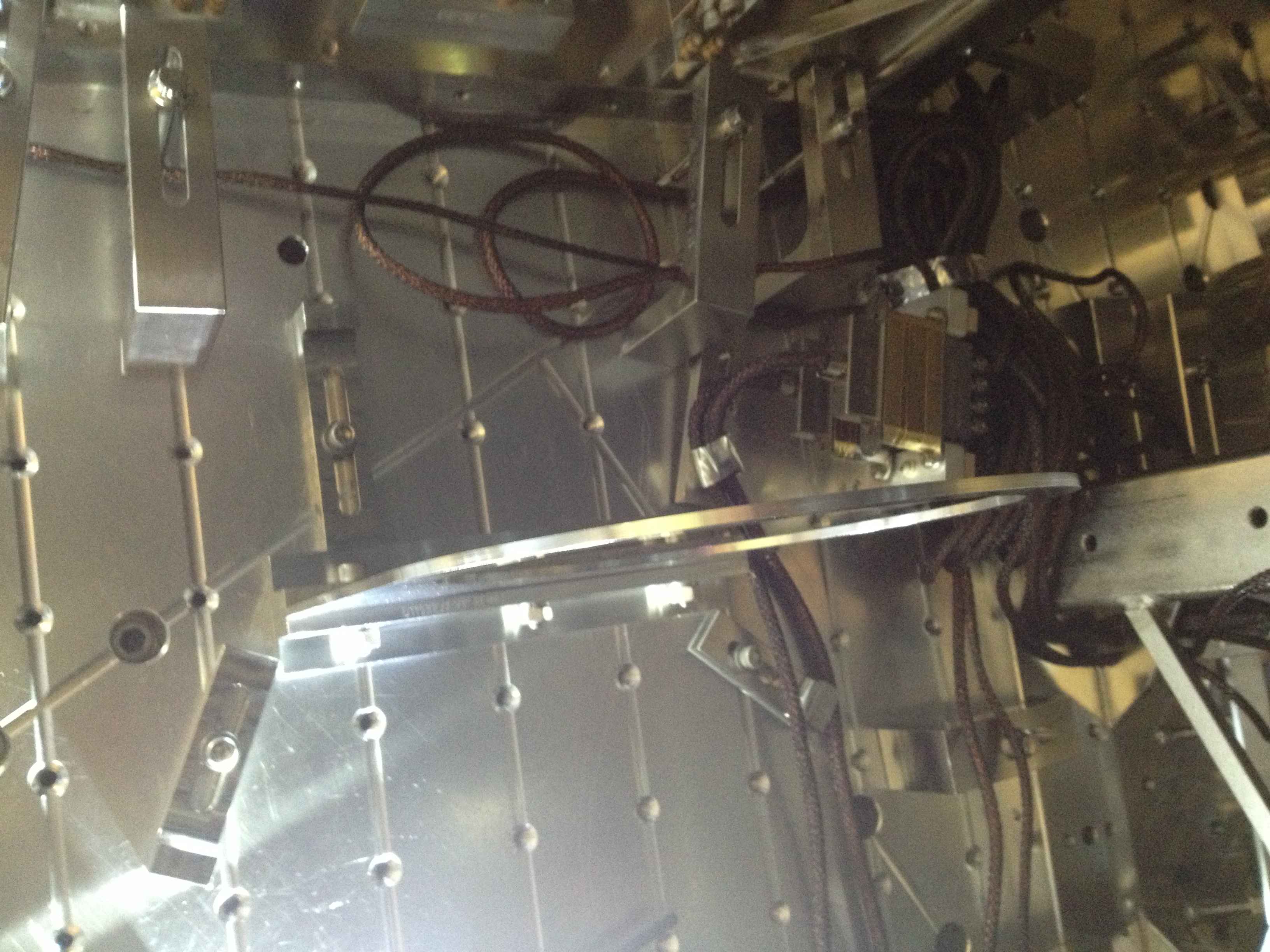
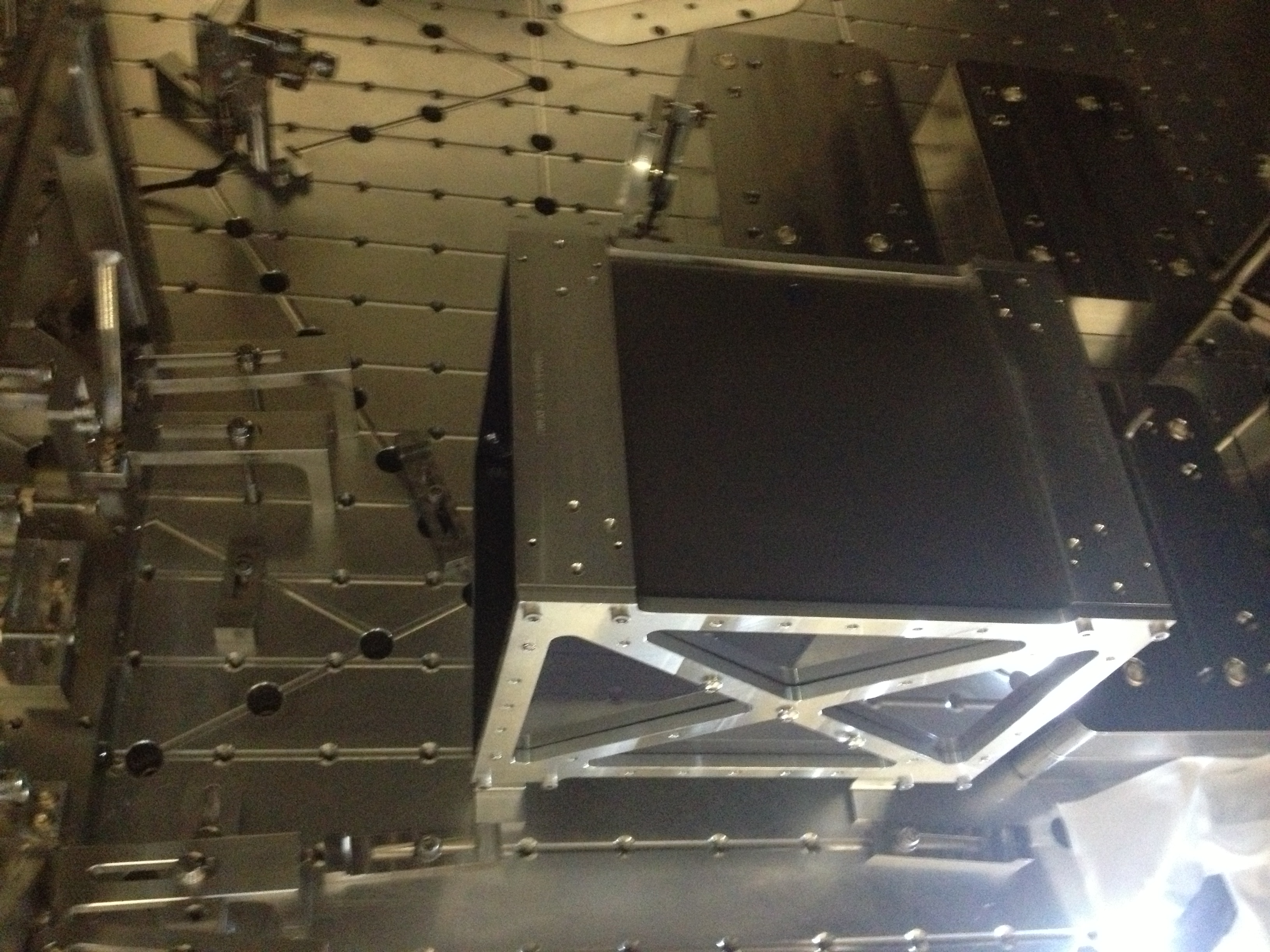
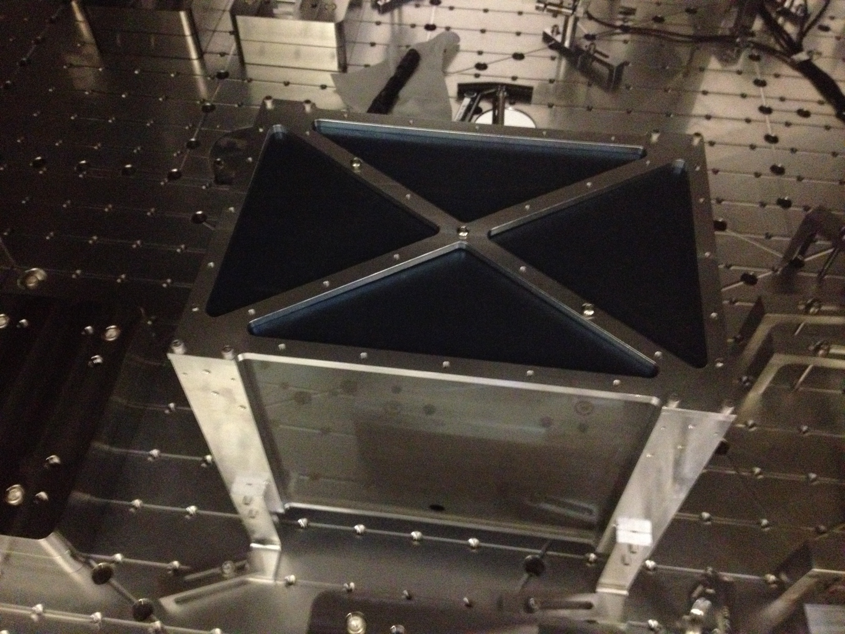
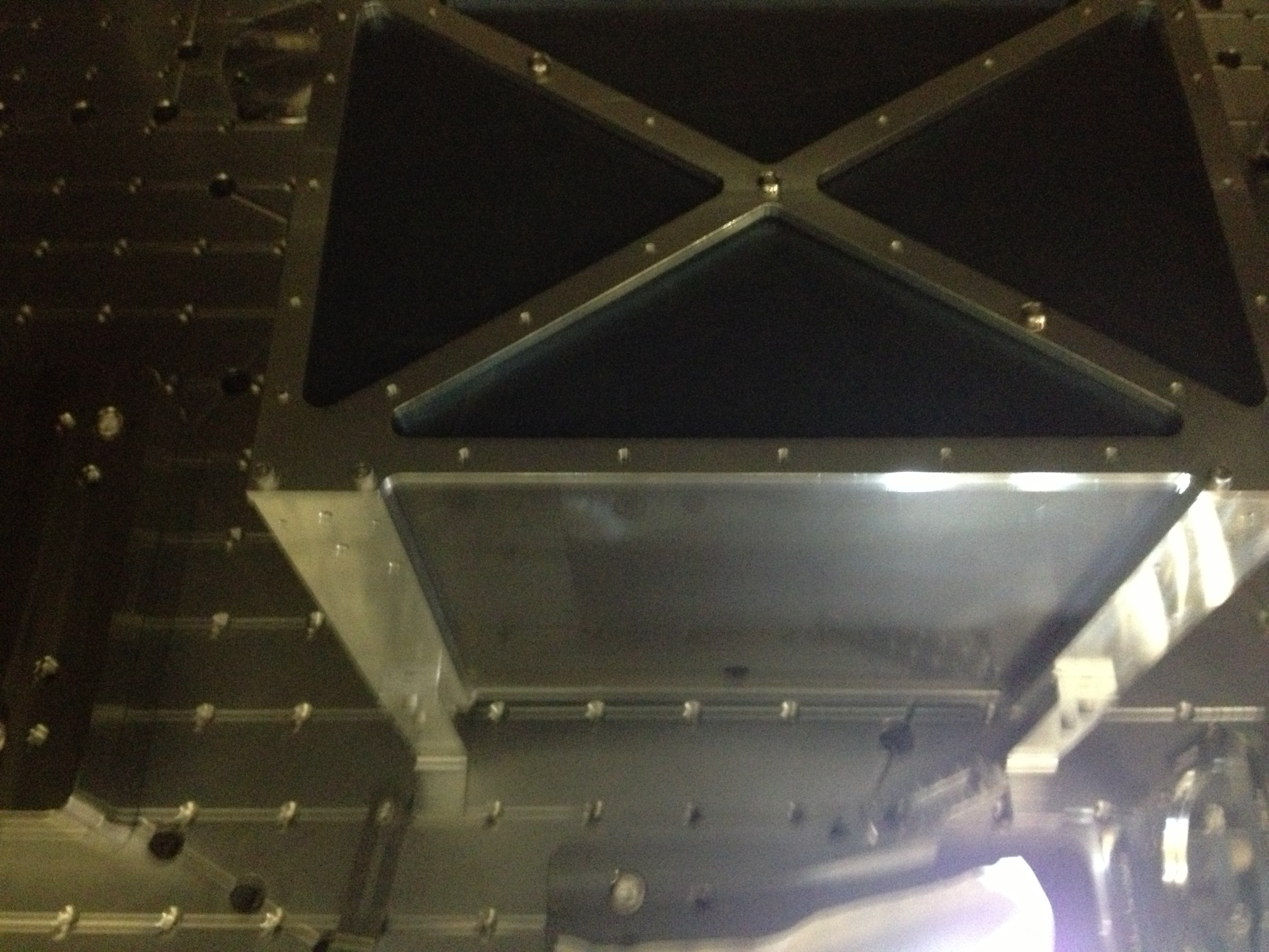
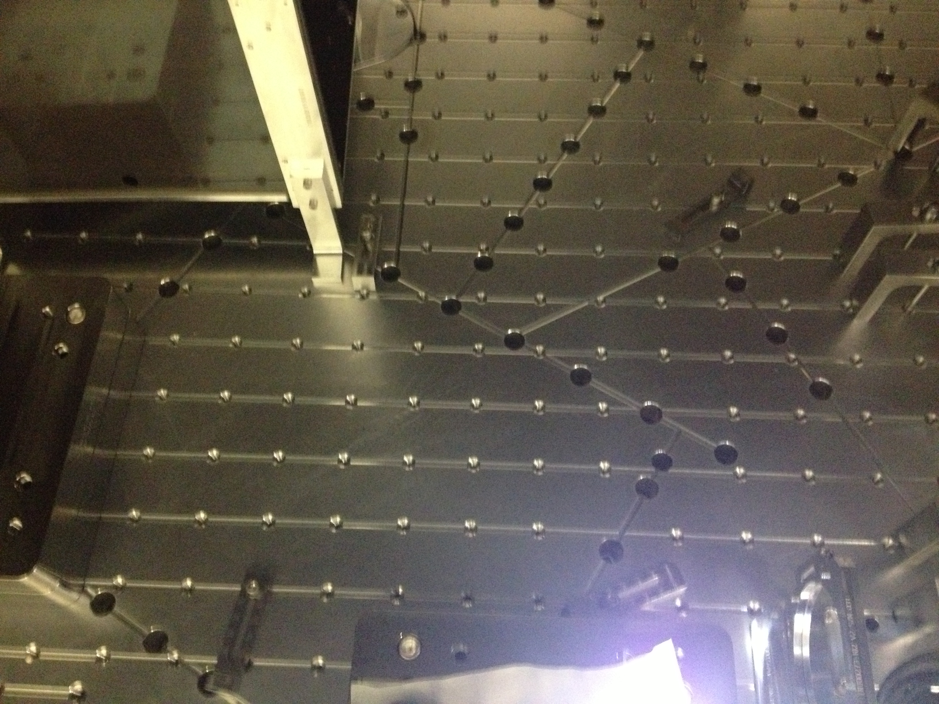
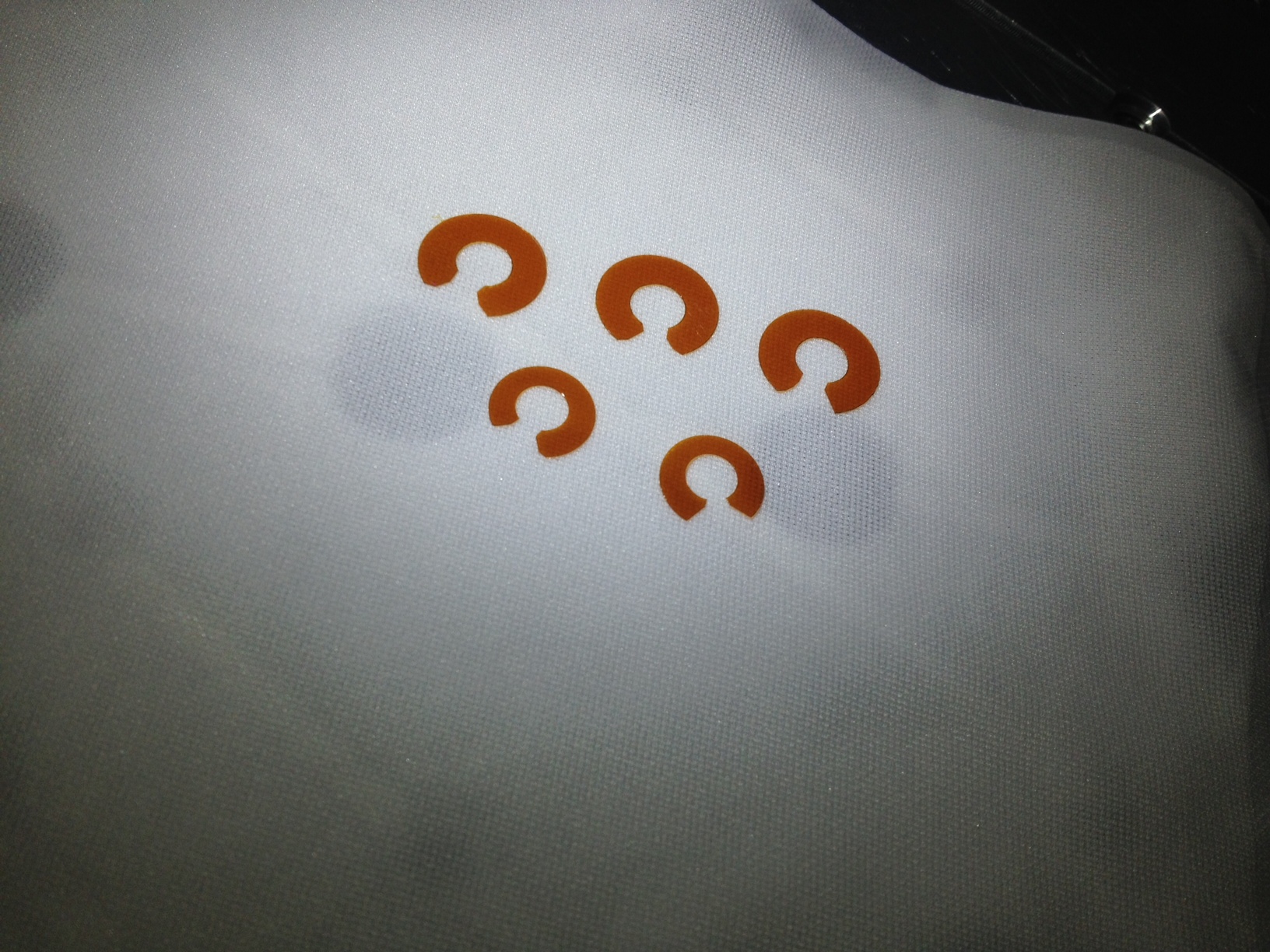
Matt, Rich

All picomotors in HAM2 have been retrofitted with Kapton washers to prevent the motor from sticking upon full insertion of the screw thread.  The process of installing the Kapton washers in HAM2 was made far easier when Matt had the good idea to cut the washers (now known as the Heintze Cut) such that they can be put on one-handed (See attached photo).  Essentially, what started as a simple washer shape ends up more like a Greek capital omega.  After that bit of cleverness, it is now possible to actually put the washers on all the picomotors in HAM2.  All washers should be so cut from now on.

While in HAM2, I had a chance to see the ISS array cabling.  Given the constraints, what has been done is about as good as can be done.  A decent cable strain relief has been implemented.  Unfortunately, as the PSL folks well know, there is really not much holding the connectors in place.  Just prior to closing this chamber, it's essential to gently verify the connectors are fully seated as I found two that were not fully engaged.  Matt mentioned how the halogen flood lights can be used to illuminate the array such that it's possible to see the 120Hz detected by each PD; this should also be done prior to final closing.  It's suboptimal, but it's what we have.
Images attached to this report
Comments related to this report
The cutting of the washers make it easy to put on the "small" or the "large" sized washers cut.
And in terms of the ISS array...Rich did mention to me that we should cut the excess off the peek cable ties. So if someone can get me some clean side snips I will do so tomorrow.