[Alexa, Dan, Masayuki, Kiwamu, Keita, and Koji]
(updated 8:15AM, correction of the window deflection angle)
HAM6 alignment work is in progress. The beam reached to the OMC but not aligned to the OMC QPDs yet.
Here is more details of the work done on Aug 11.
= Guiding the beam to HAM6 =
The beam was guided to HAM6 by centering the beam on the SRM. By shaking the SRM alignment in pitch and yaw, we could confirm
how the spot was centered. In reality, we initially suffered from not noticing intentional misalignment of PR2. Once the PR2 alignment was
restored, it was not so difficult to find the spot around the SRM aluminum holder.
= Locating the beam axis at the center of the clear aperture =
Once the beam was found in HAM6, we again shook the SR2 to find the aperture free from clipping by the SRM or OFI.
The beam was settled at the center of the clear aperture.
Note: this does not necesarily mean that the beam is still at the center of the SRM.
The beam coming in the HAM6 chamber has in deed a different angle from the design layout (D1000342).
The beam entrace point is located almost as designed. At the edge of the table the beam height was 97.5mm (3.84"). This already suggests the
beam is downward. The beam is angled not only in vertical, but also in horizontal. At the position of the OM1 tip-tilt, the beam is 2" to South
(towards OMC) and 0.5" too low. This angle is, in deed, 32mrad and 8mrad, respectively. This couldn't only be caused by the spot location on SR2
as it requires tens of cm shift on SR2. Therefore we suspected any wedged optics around HAM5, which means the septem window and
wedged prisms in the OFI.
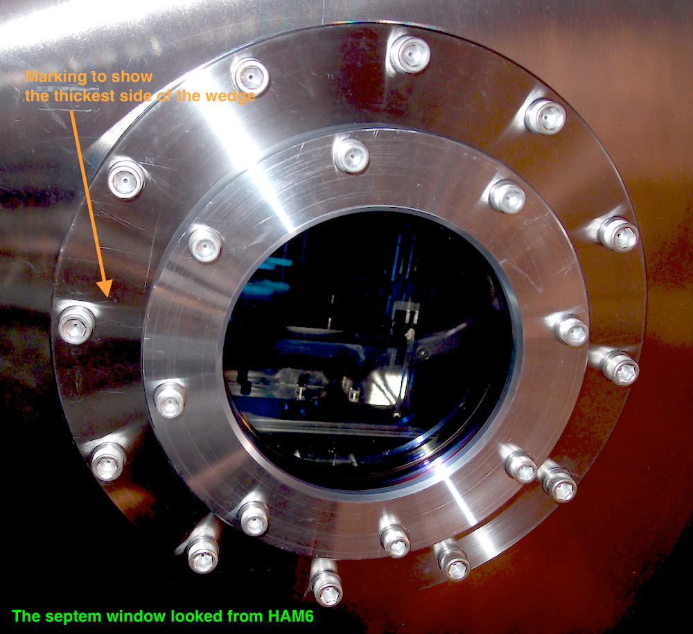
Keita called LLO and confirmed they had similar horizontal beam shift but observed no vertical shift. This may mean that the horizontal angle
is a systematic effect. We confirmed the wedged window is installed so that it wedges almost horizontally (see attached photo).
Keita calculated the wedge effect of the septem to be 6mrad. This is not enough to explain the angle we actually saw.
We also wondered how the wedged prisms are installed in the OFI.
We checked if the beam power does make sense or not. The detected power right after the spetem was 3.2mW. This is reasonable as it is
not so far from the expected value of 4mW. [1.9W (Pin) x 0.8 (IMC) x 0.03 (PRM) x 0.35 (SRM) x 1/4 (Michelson) = 4mW]
= OM1 Tip-tilt / OM1 transmission path (AS_AIR and AS_C QPD) =
For now, we decided to continue to align the other optics. Firstly, we moved the OM1 to South (towards OMC) by 2".
The transmission path of OM1 had to be moved by 2" as well. This actually causes the counter mass moved towards East door by 2".
Therefore the table balance has to be reviewed eventually. The other steering mirrors were also moved as well. The first two steering mirrors
after OM1 had to be largely angled in pitch to absorb 8mrad beam tilt at OM1. The beam was centered on the last steering and the beam is directed
to AS_C QPD. We used CDS to finely align the beam on the QPD. The beamsplitter before the last steering was aligned such that the beam exits
from the enter of the window emulator.
The beam diverter and its beam dump were aligned. The beam diverter is open when the mirror is at the west side (HAM5 side)
and is closed when the mirror is at the east side (East door side).
= OM1 Tip-tilt alignment =
OM1 was moved so that the beam hit the center of OM2. This requred OM1 facing upward to compensate the vertical angle of the incoming beam.
This was done by the counter balancing screw on OM1. The range was not enough only by moving the screw, the screw was inserted from the back
to give more weight at the back side of OM1.
= Fast shutter / beam dump =
The fast shutter could not be placed at the planned place as the body structure of the shutter blocks the incoming beam.
The shutter was placed west side (HAM5 side) of OM3 rather than the east side. The upwarding beam in this path caused the fast shutter reflection
going up. This caused the beam on the beam dump too high by 1". This needs to be fixed before closing the door.
= OM2 alignment =
OM2 was rotated in yaw in order to accommofate the spot on OM3. The natural misalignment of OM2 in pitch made the spot on OM3 almost at the center.
= OM3 alignment =
We rotated OM3 to hit the input mirror of the OMC cavity. The OMC REFL beam was found. We did not hit any of the OMC QPDs yet.
= Beam clearance =
In the end, the beam is enough away from the tip-tilt cages desppite the move of the incoming beam.
The distance between OM2 and the incoming beam is about 2". The one between OM3 and the incoming beam is about 2.5".
The distance between OM2 and the relfected beam from OM1 is about 0.5" while the beam size there looked less than a mm.
= Adding dog clamps =
The many of the optics on the table was fixed only with one screw or a dog clamp. We started to add more clamps to them. It's not complete yet.