Came on site to resolve this issue. Console for h1sush2b shows many errors and is frozen. First recovery attempt is a power cycle of the front end computer.
First removed h1sush2b from the Dolphin IPC network using h1susb123 as a remote disabler, this worked.
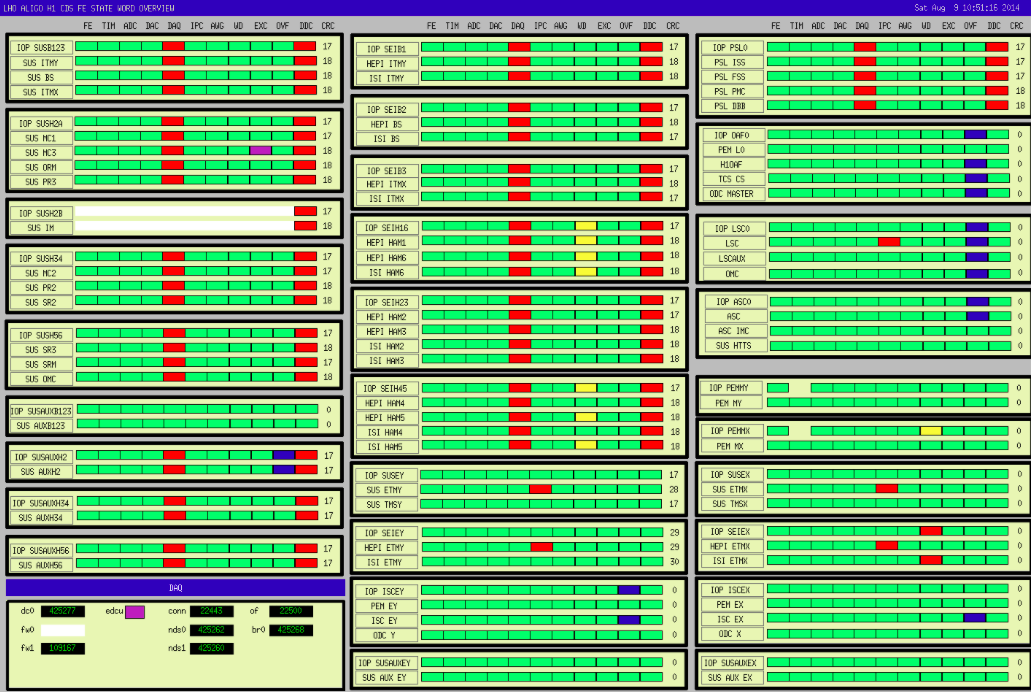
Power cycled the computer, let the models start themselves. As I suspected, h1sush2b was actively corrupting the DAQ data streams to the concentractor. As soon as h1sush2b was powered down all front ends DAQ data became good again.
IOP model started with large IRIG timing error, daq status 0x4000. Stopped h1susim and restarted h1iopsush2b, still get IRIG-B errors. Checked IRIG-B is OK, suspect problem is at the IO Chassis end.
Step 2 was a full power down of both computer and IO Chassis. Stopped all models, and removed h1sush2b from Dolphin using itself to do this. Powered down h1sush2b. In CER, turned front panel switch to OFF, this did nothing. Disconnected the 24V-DC power cable at the power strip, noting that this was the only thing plugged into this strip (the two other IO Chassis use a different strip) maybe a hint. Powered IO Chassis backup, switch to ON, waited for timing slave to sync. In MSR power up h1sush2b, both models start with no errors.
So not sure why h1sush2b died, but suspect a glitch in CER at 00:08 this morning.

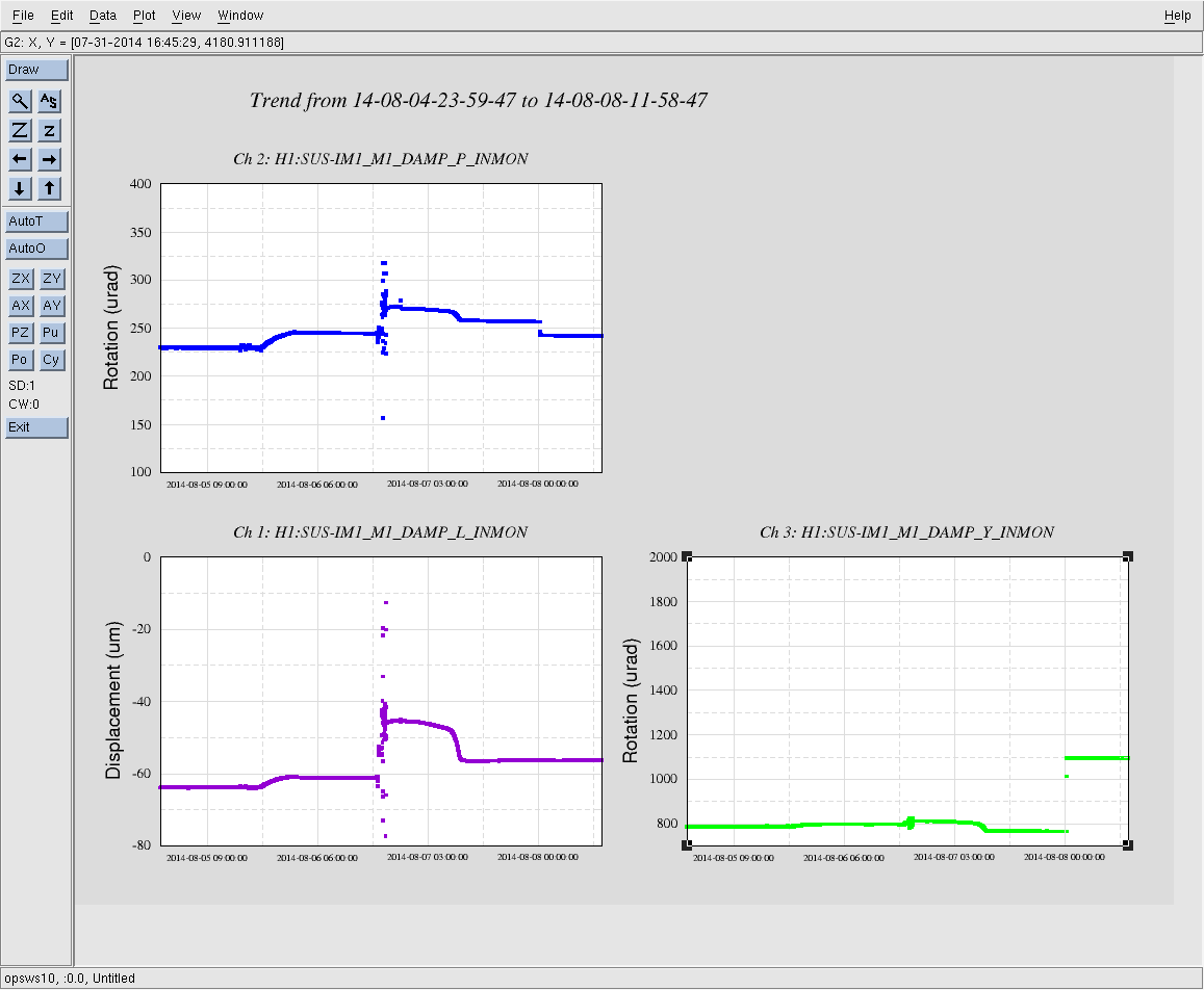
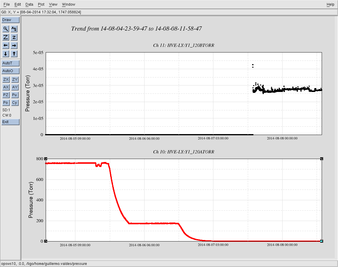

for the systems whose DAQ data was corrupted, the time period we have no data is:
00:06 - 11:50 PDT August 9th.