(Stefan, Kiwamu, Koji, Alexa)
We repeated the ringdown measurement with the low gain setting (0dB compared to the nominal 30dB) and the ND0.6 filter removed (we still need to eventually revert to the nominal configuration). This time we found that the ringdown time was approximately 25µs, which is still larger than what we expected. We want to repeat this measurement with REFL from ISCT1, however, we could not find the beam for a while and then got distracted with other things...This is still to be done.
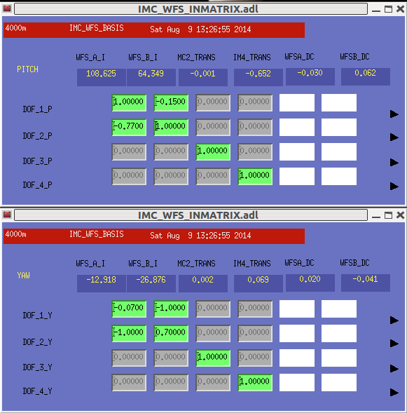
We adjusted the gains, phase rotation, I-Matrix and IMC WFS matrix. We can now engage the WFS; this increased the trans PD to ~1200 and was stable. I have attached a screenshot of the current configuration.
We increased the PSL power to 1.9W.
The beam is too high on MC3 by 1.5mm and horizotanlly off by 2.138mm in the direction away from IOT2L. This result is almost the same as the previous measurement in alog 8943, so we are fine with this off-centering.
(Richard, Cyrus, Alexa. Kiwamu)
GigE camera 08 of PR2 was first rebooted and then had to be adjusted because the image was clipped.
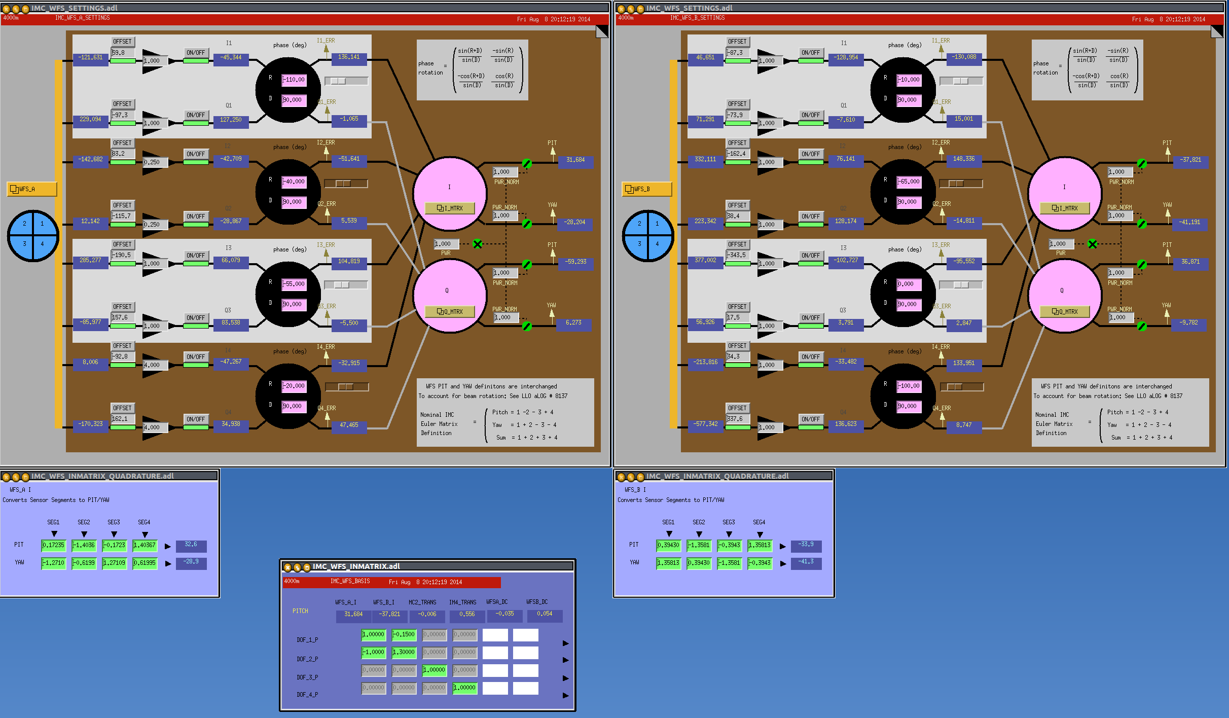
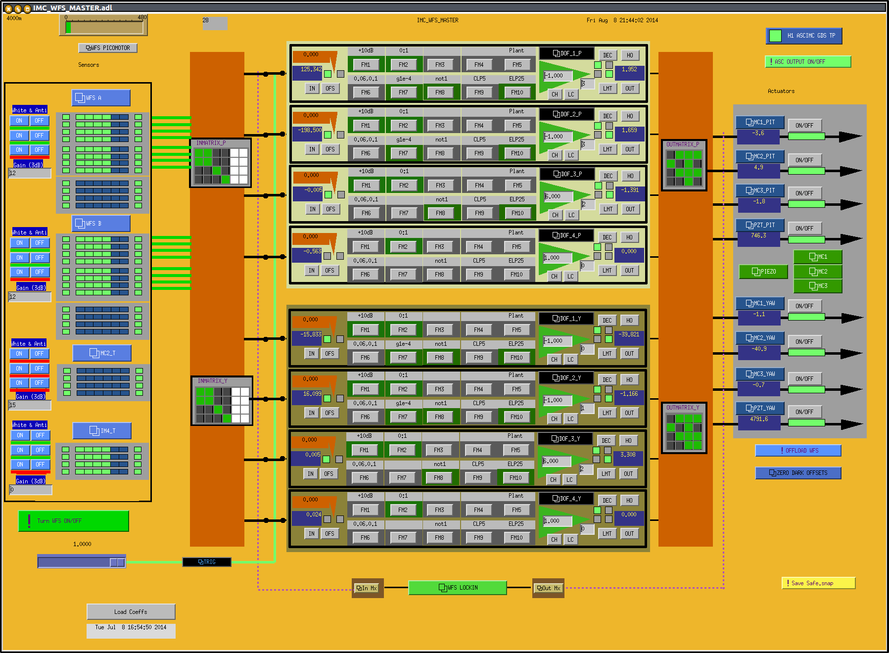
I have cleaned up the input matrix for the IMC ASC loops. They are now normalized such that the leading elements are normalized to 1, rather than having a random gain. I did not change the servo gains.