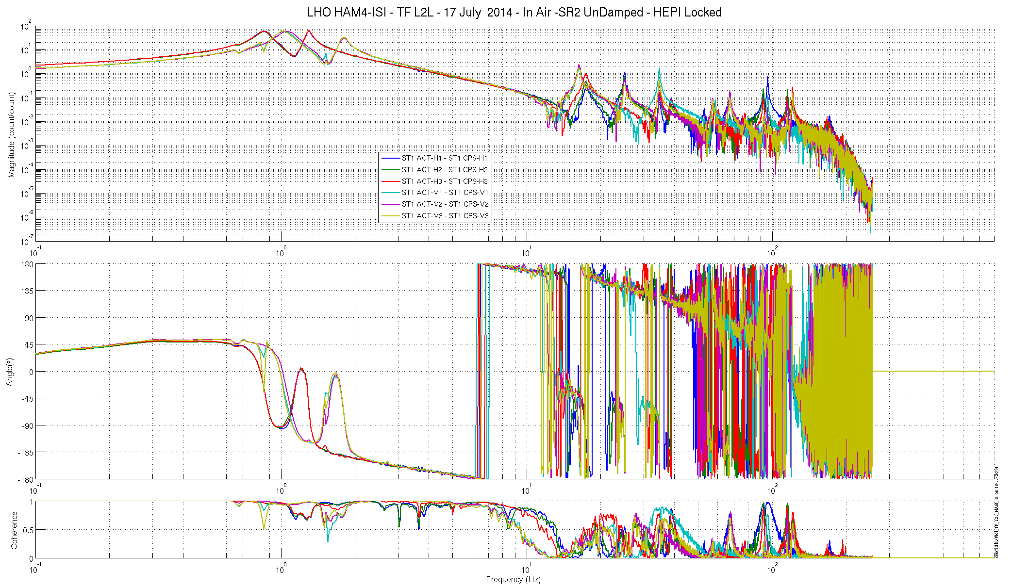
Particle counts for this afternoons session in HAMs 4 and 5
HAM4
Cleanroom start of session
All zero counts.
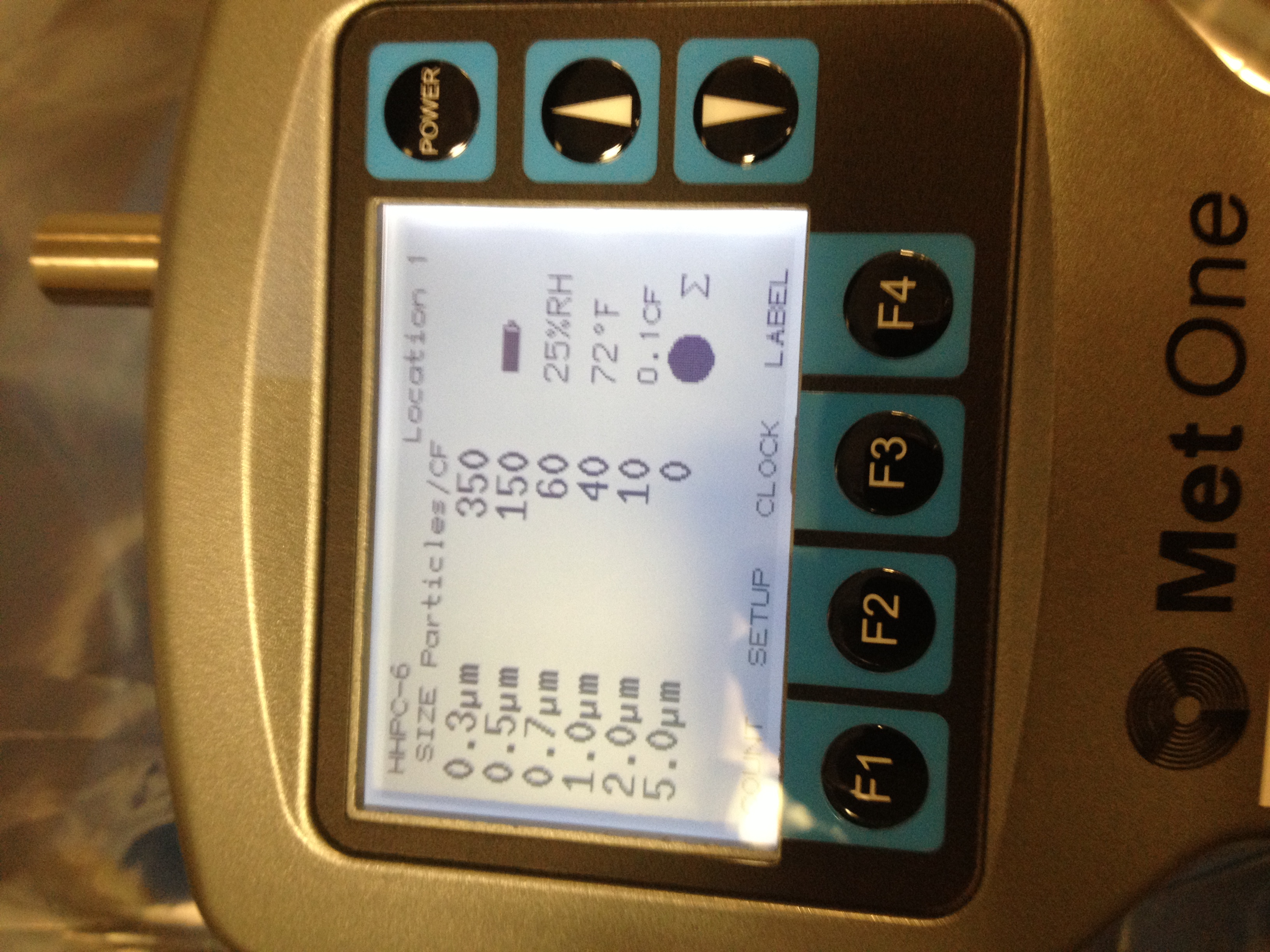
Chamber start of session:
0.3um....350 counts
0.5um.....150 counts
0.7um...60 counts
1.0um....40 counts
2.0um...10 counts
5.0um...0 counts
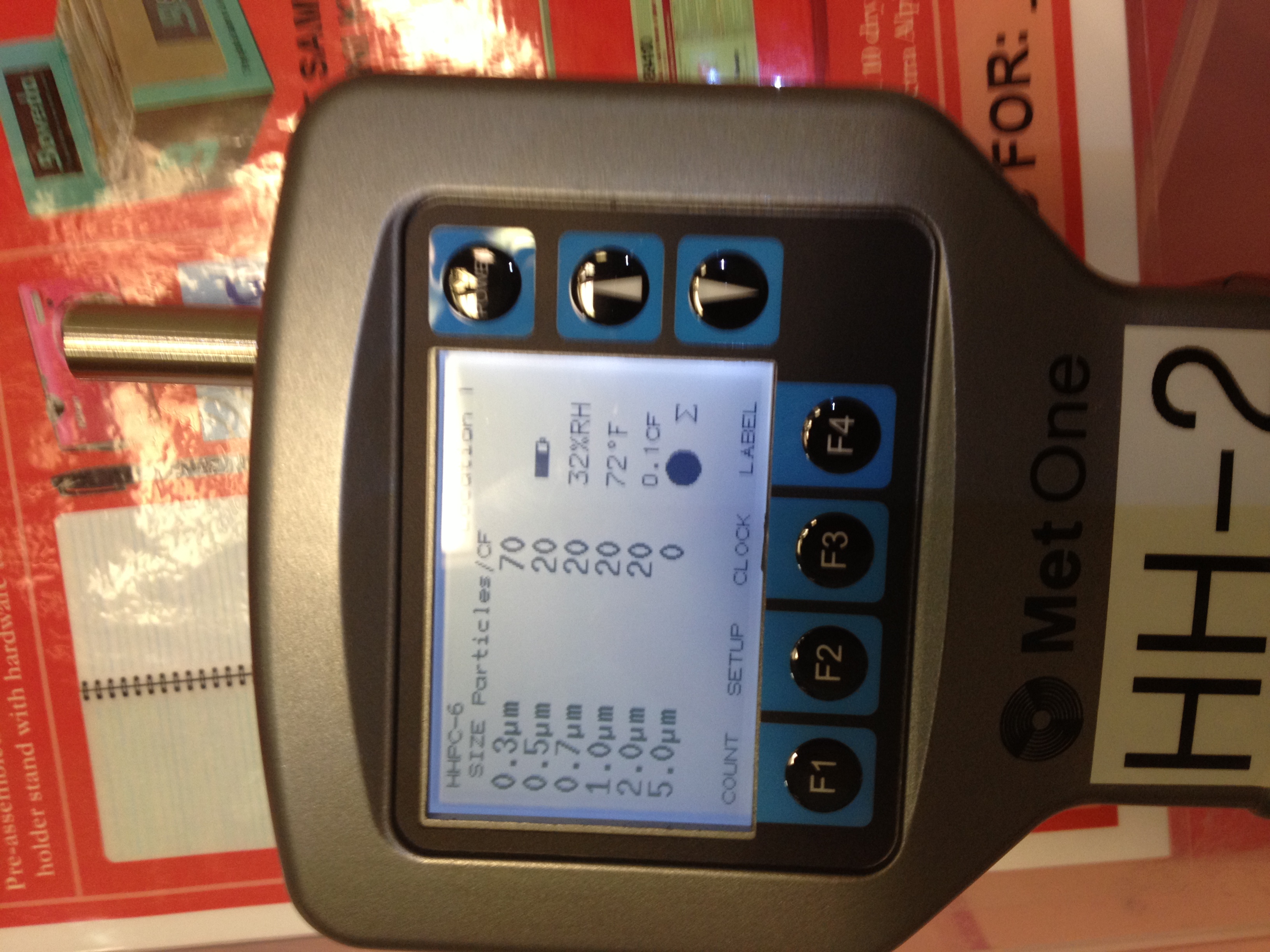
Chamber end of session
0.3um....70 counts
0.5um...20 counts
0.7um.....20 counts
1.0um....20 counts
2.0um....20 counts
5.0um....0 counts
HAM5
Cleanroom start of Session
All counts zero
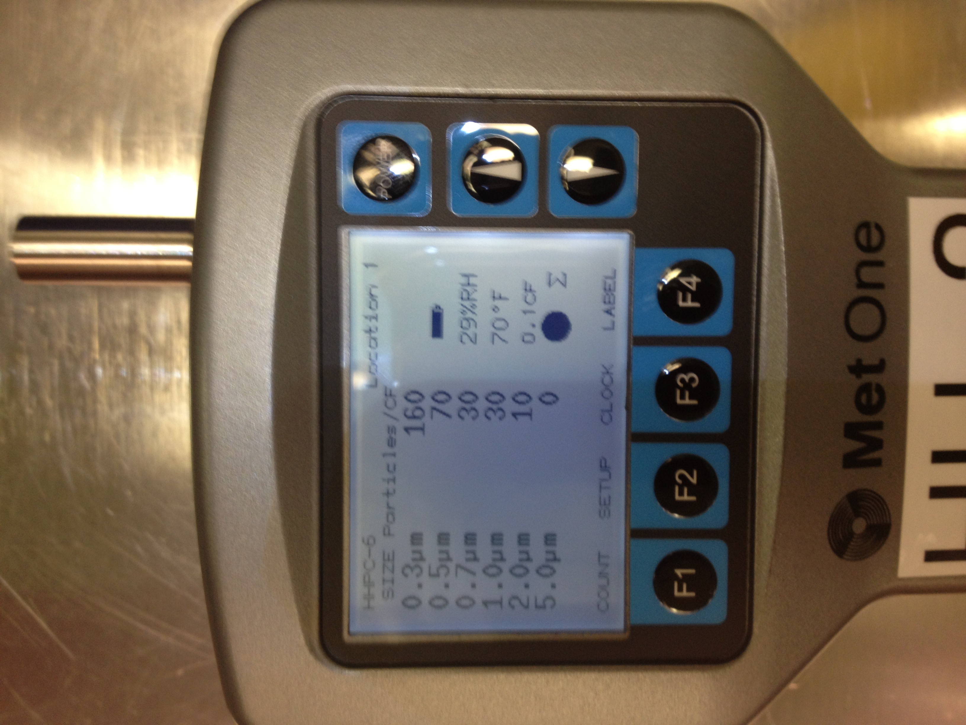
Chamber start of session
0.3um....160 counts
0.5um....70 counts
0.7um....30 counts
1.0um....30 counts
2.0um...10 counts
5.0um...0 counts
Chamber end of session:
0.3um.....130 counts
0.5um...30 counts
Rest...zero counts
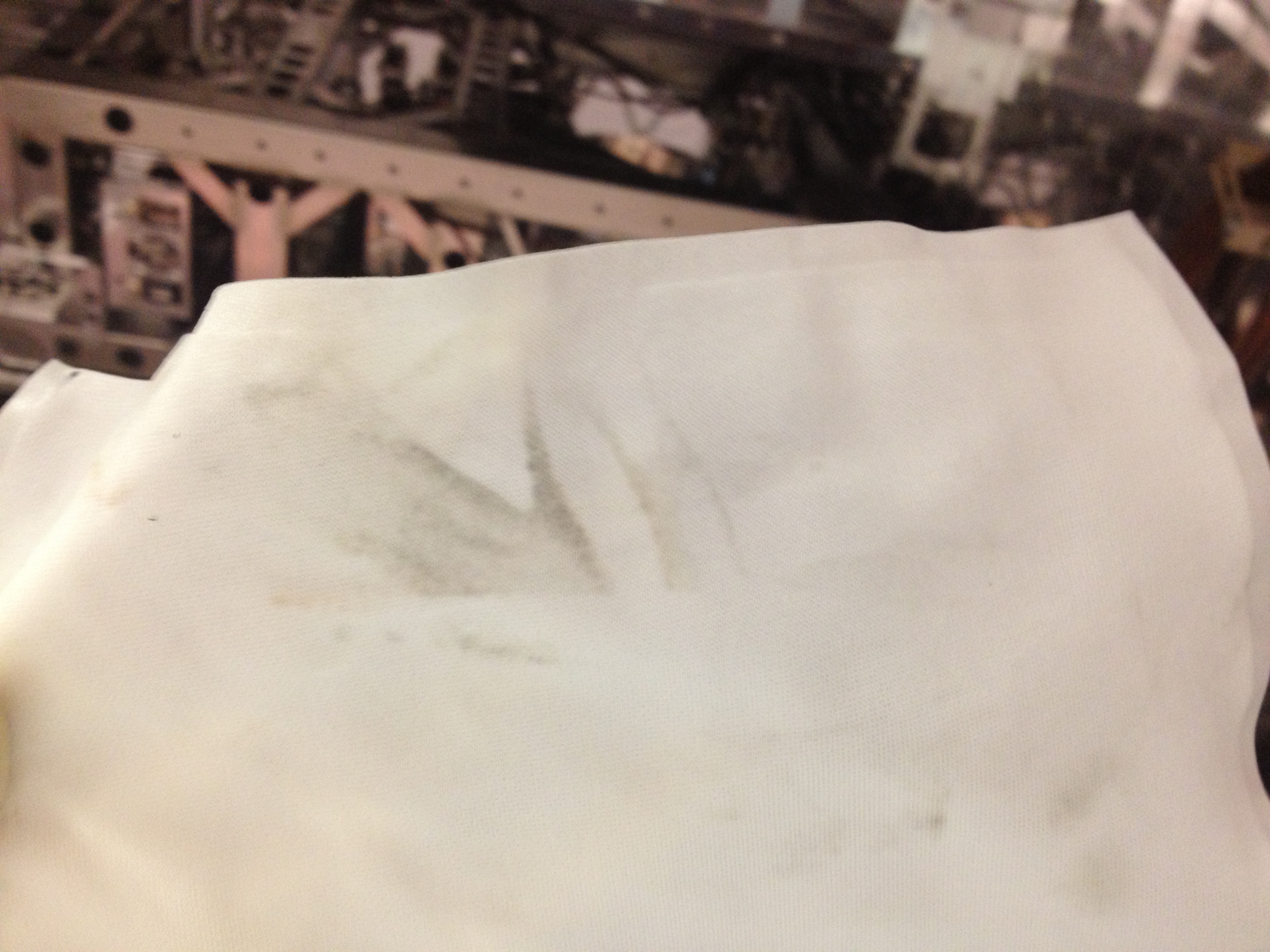
As an added note: it was interesting that I could smell the First contact as it was being applied in BSC2 all the way up at HAM5 when I was working there. Just more interesting than anything as shows how the purge can propogate stuff from that chamber all the way to HAM5
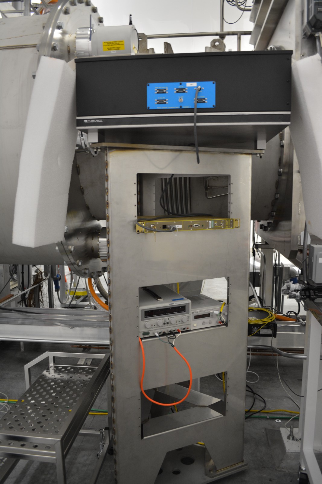
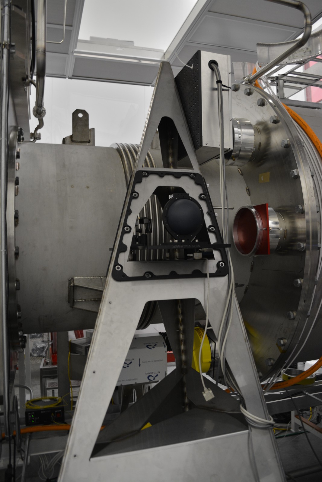
I have included photos in case people are also interested in temp or RH in chamber at time