Volker, Matt H, Corey, Rick S, Guido, Rodica (remote), Rich A (remote)
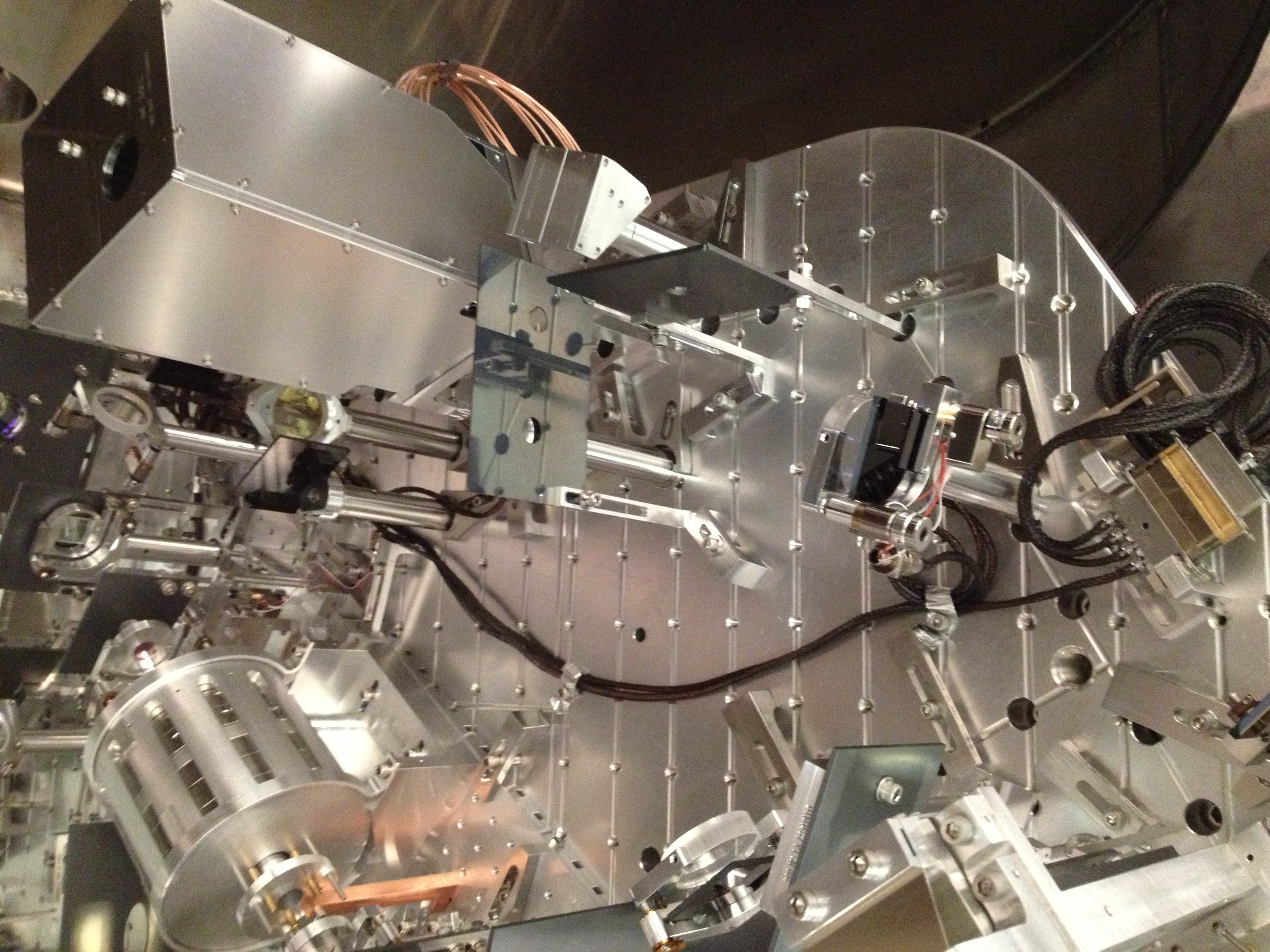
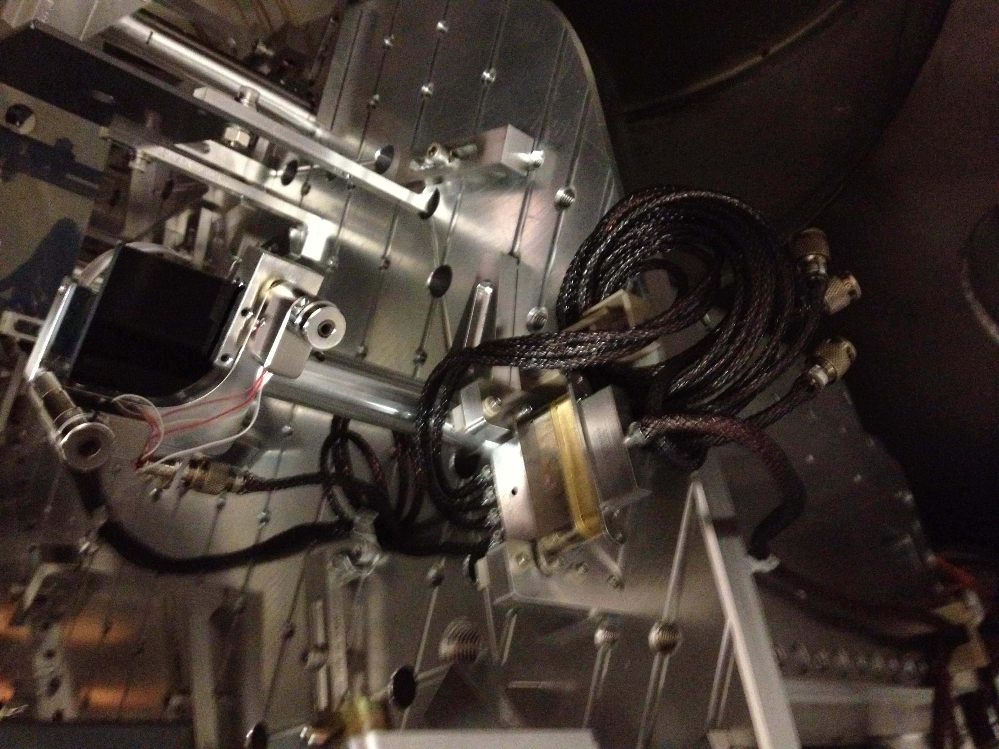
Quick summary of work on the ISS array this week (I will write a more detailed alog later with details on cabling, mode matching, lens/mirror/ISS array positions, what optics used, photos, etc)
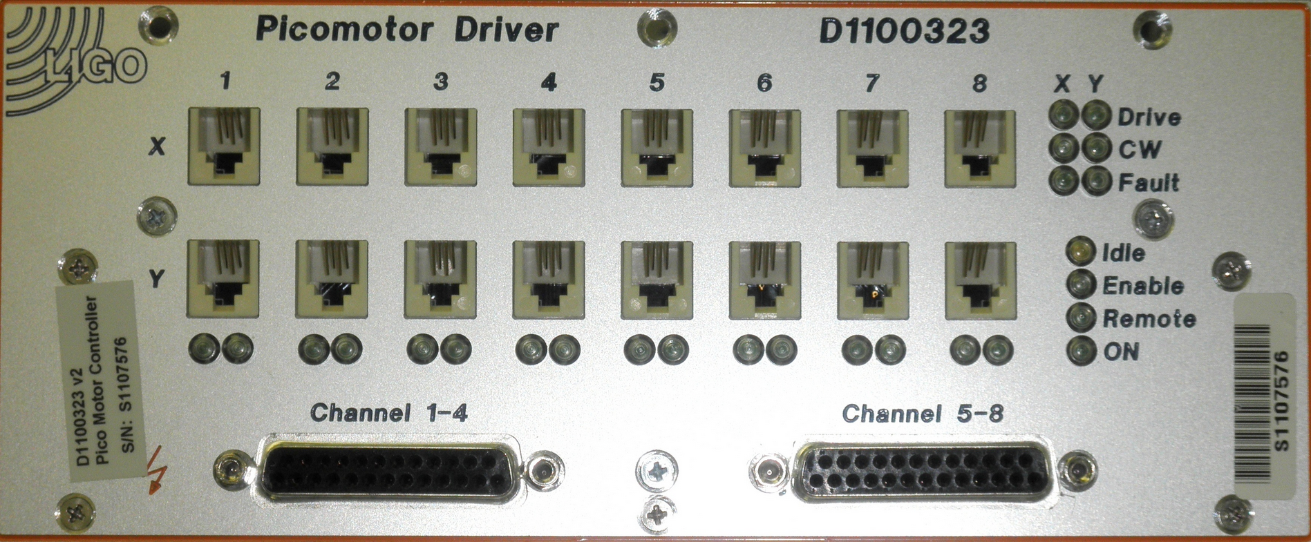
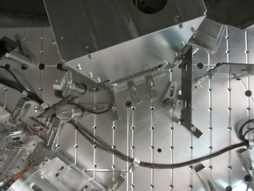
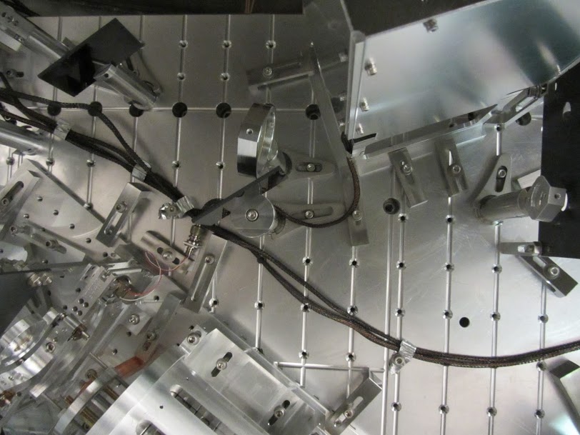
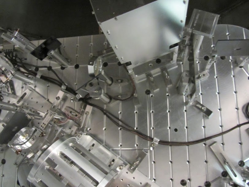
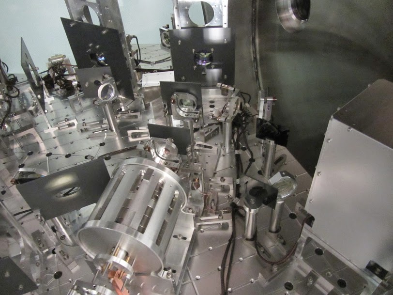
The beamsplitter mount ROM RH4 on HAM2 was swapped out for one that was controllable with pico motors. The in-air cabling was hooked up to a feedthrough port and tested with a temporary setup controlling it on the in-air side. All degrees of freedom work.
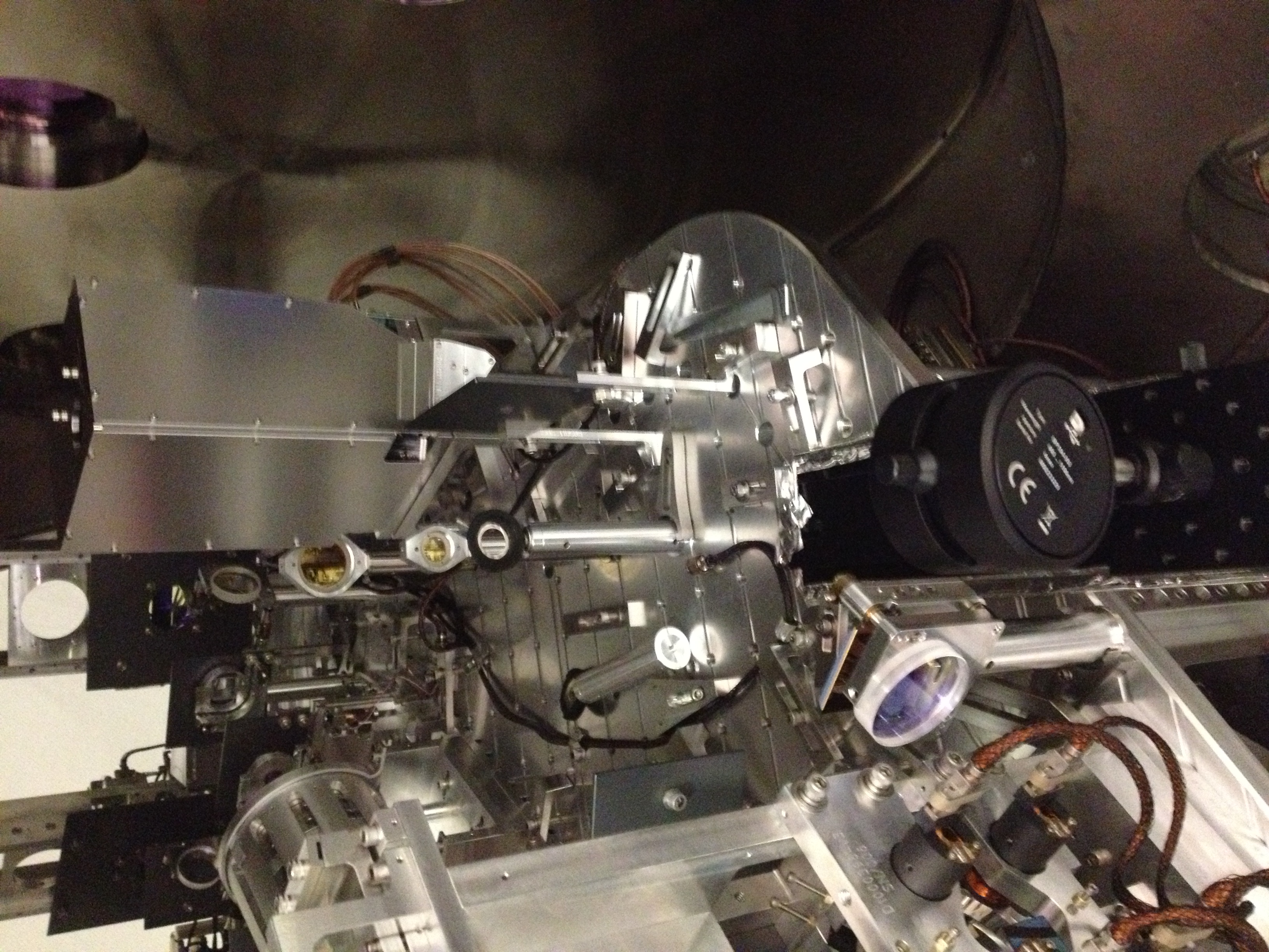
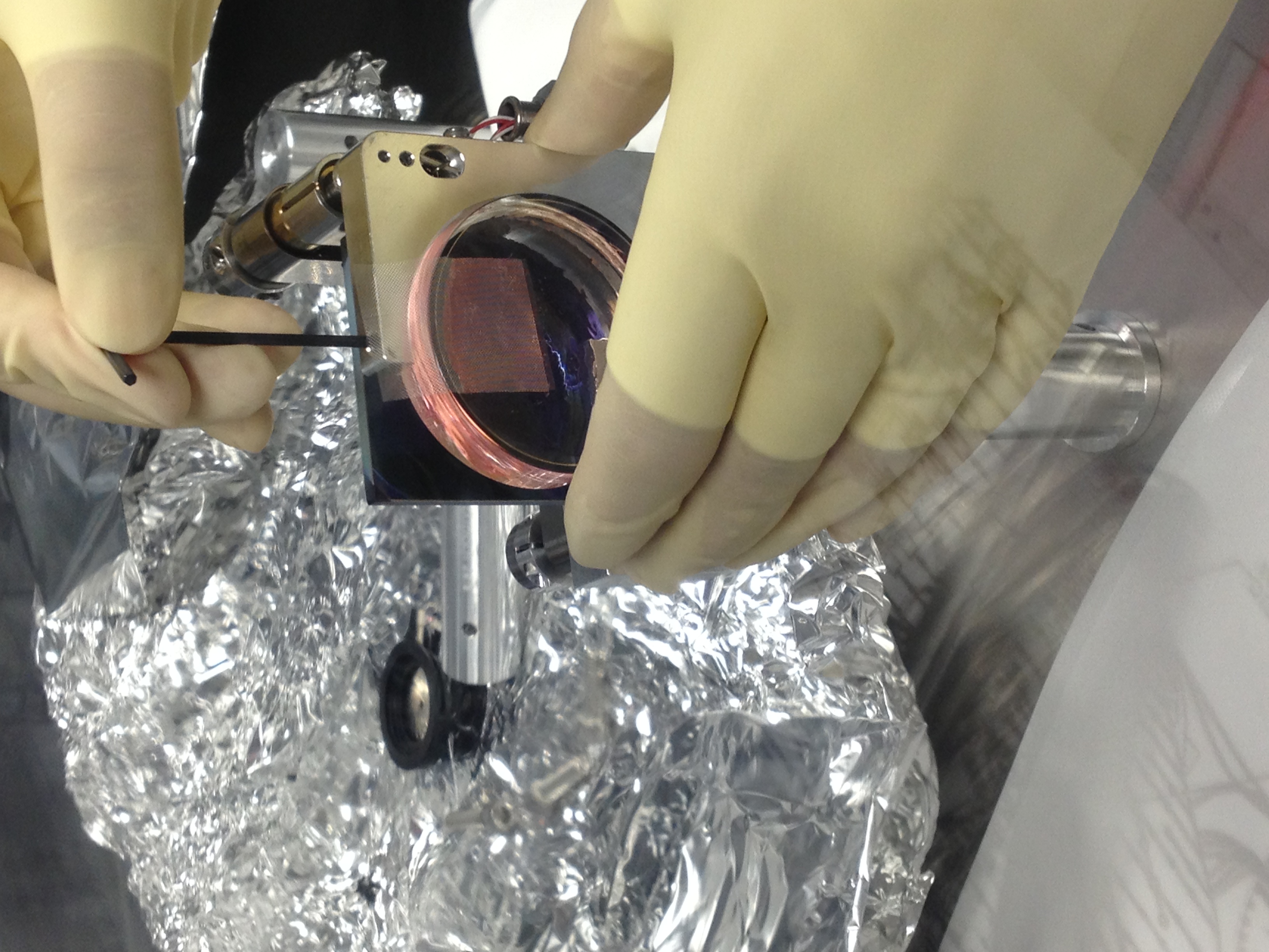
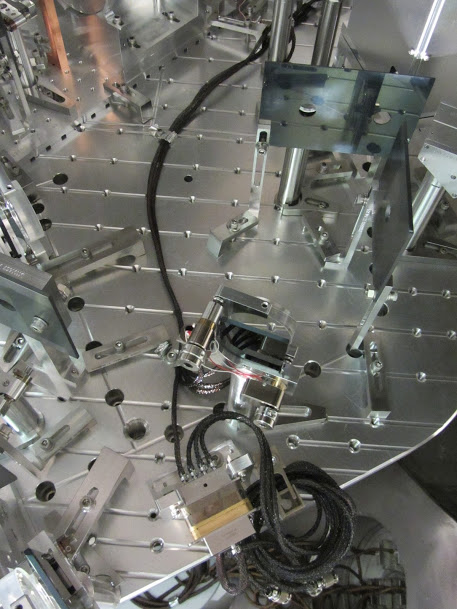
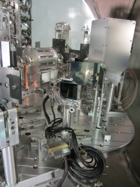
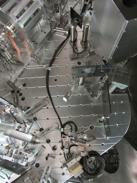
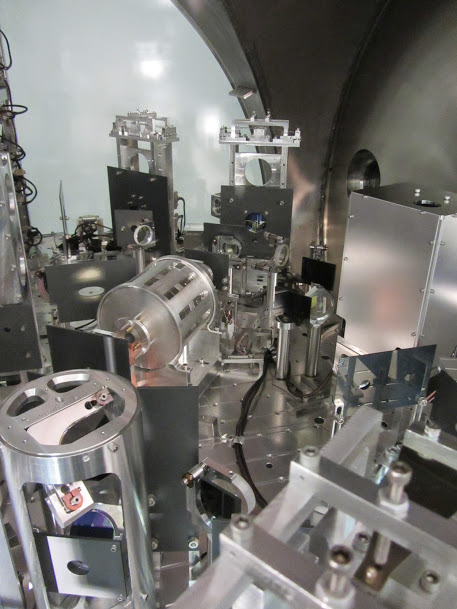
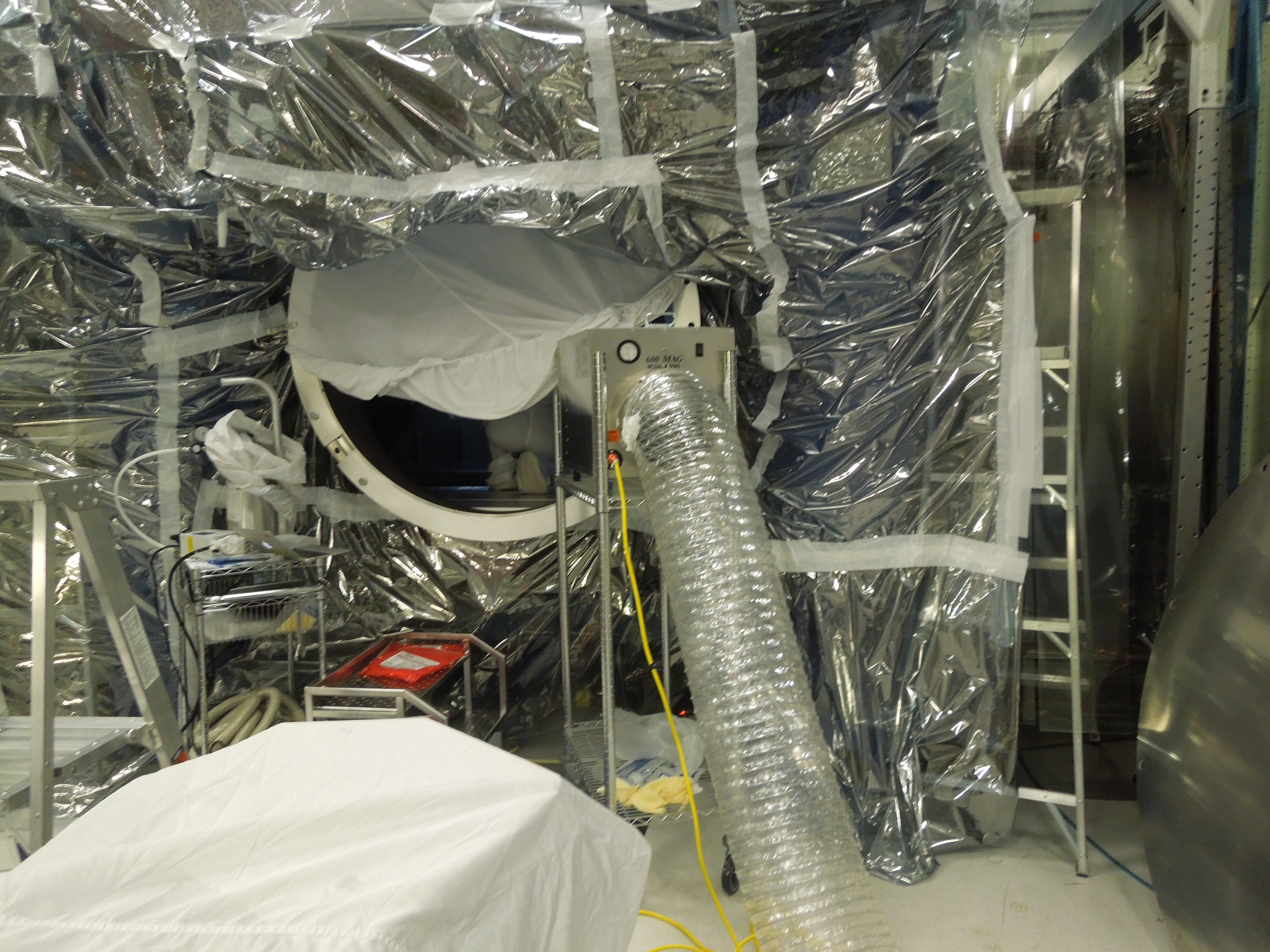
Lots of work was spent getting the lenses in the correct spot so that the beam waist and position was in the correct spot, no clipping, etc. The mirror in AROM RH2 was swapped for a flat mirror and the beam is now directed onto the entrance aperture of the ISS array. The lenses were tilted off axis a little bit to make sure no back reflected beam went directly back into the system and black glass beam dumps were installed to try to catch these back reflected beams (positions guessed as we cant see the back reflected beams).
We had to move a couple dumps/baffles into slightly different positions to make things fixed and we had to alter the in-air cable dressing that was done previously as it went right where we wanted to put stuff. All cables have been redressed up to the feedthrough but NO ground loop hunting done on cables yet. SEI personnel might want to check my cable routing from feedthrough to stage zero to stage 1 on the ISI, but I am pretty confident its okay.
Next week.....trying to get the quadrant detector and photodiodes aligned
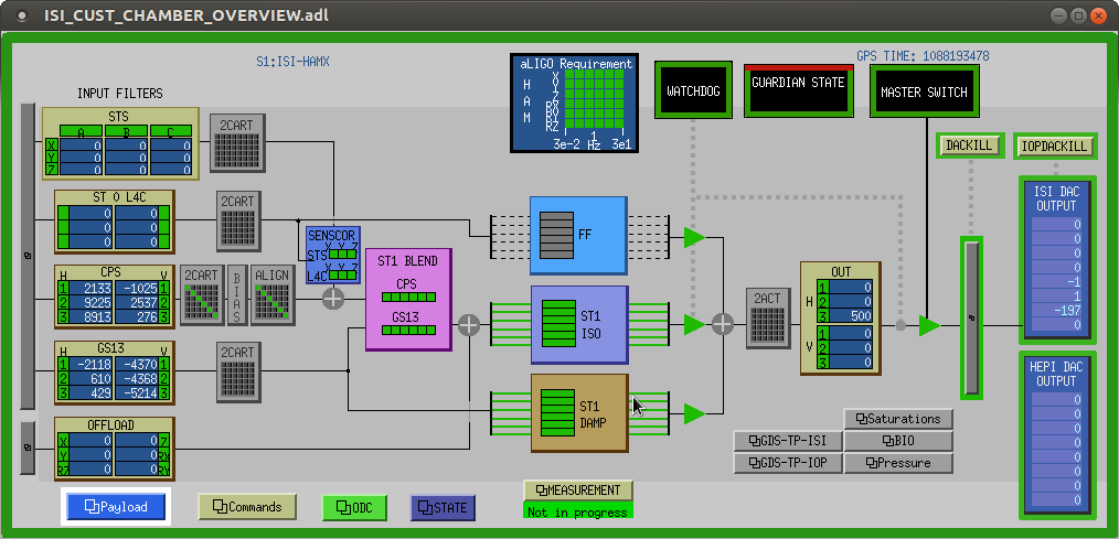

More transfer function measurements were taken on the lower stages of ITMX last tuesday.
Interesting things to notice :
1. The measurements with no top mass damping (1st and 3rd attachments) appear to show resonnances which are not predicted by the model. Those are most certainly resonnances of the reaction chain moving because of the reaction force (e.g. 3rd page of 1st attachment : resonnance at 0.66Hz is not predicted by the model, but matches with the frequency of the first yaw mode measured on the top mass reaction chain, cf this measurement from alog 12555).
2. There is a factor of 2ish discrepancy between the model and the measurement for both UIM and PUM