J. Kissel, D. Barker
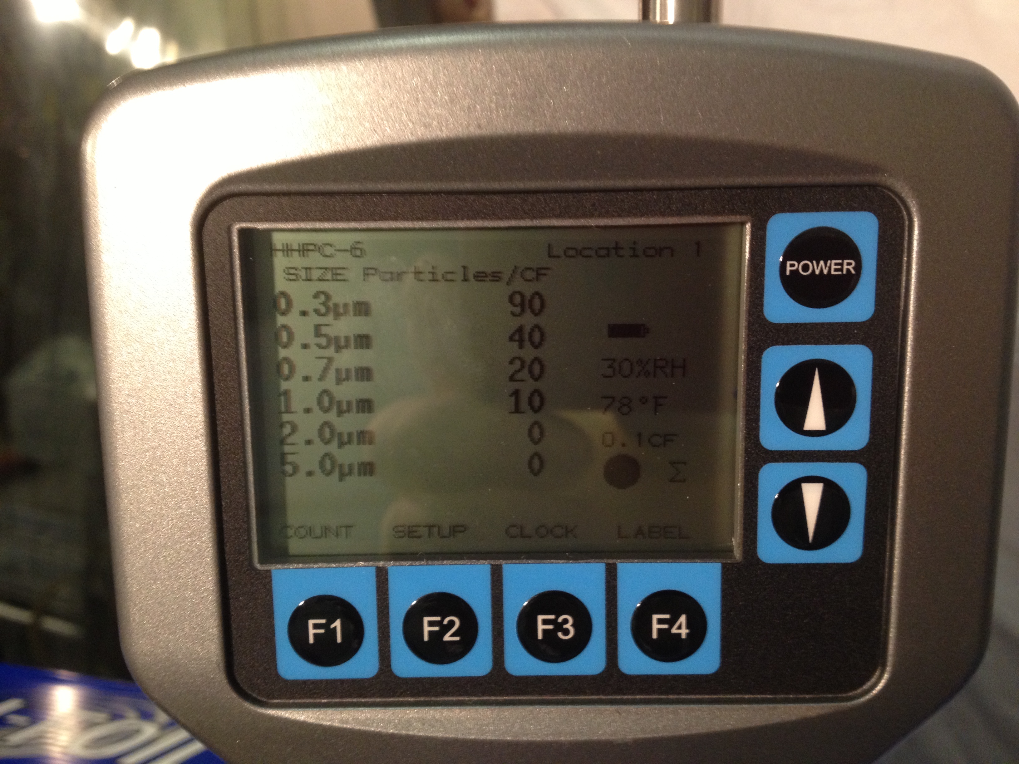
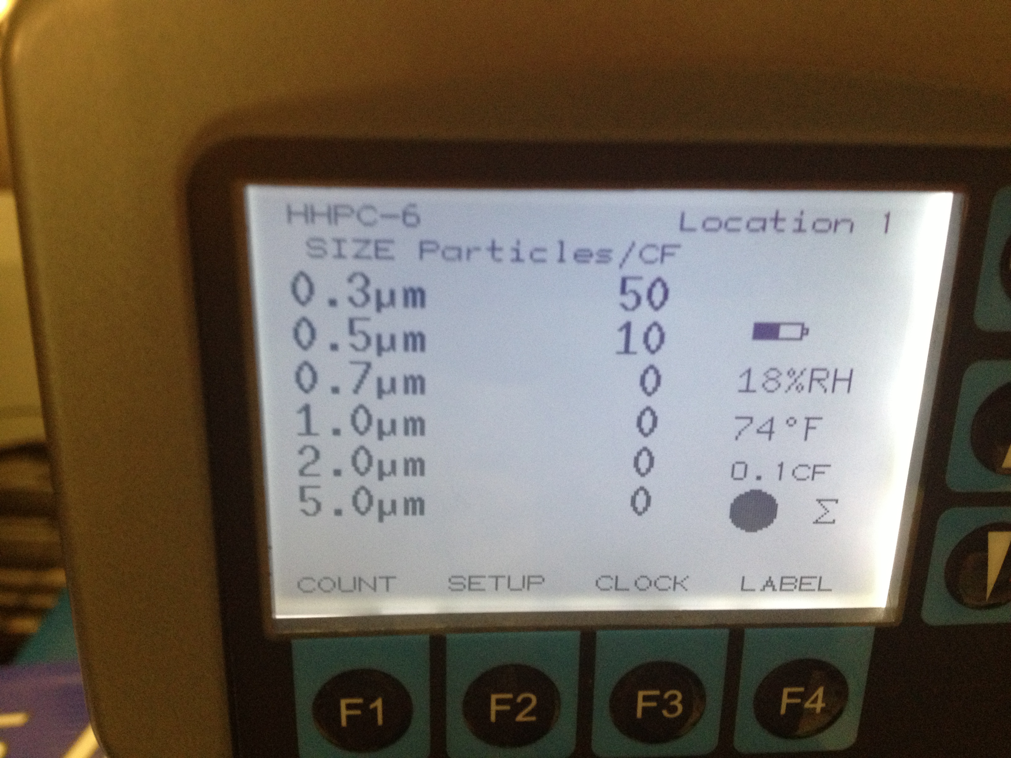
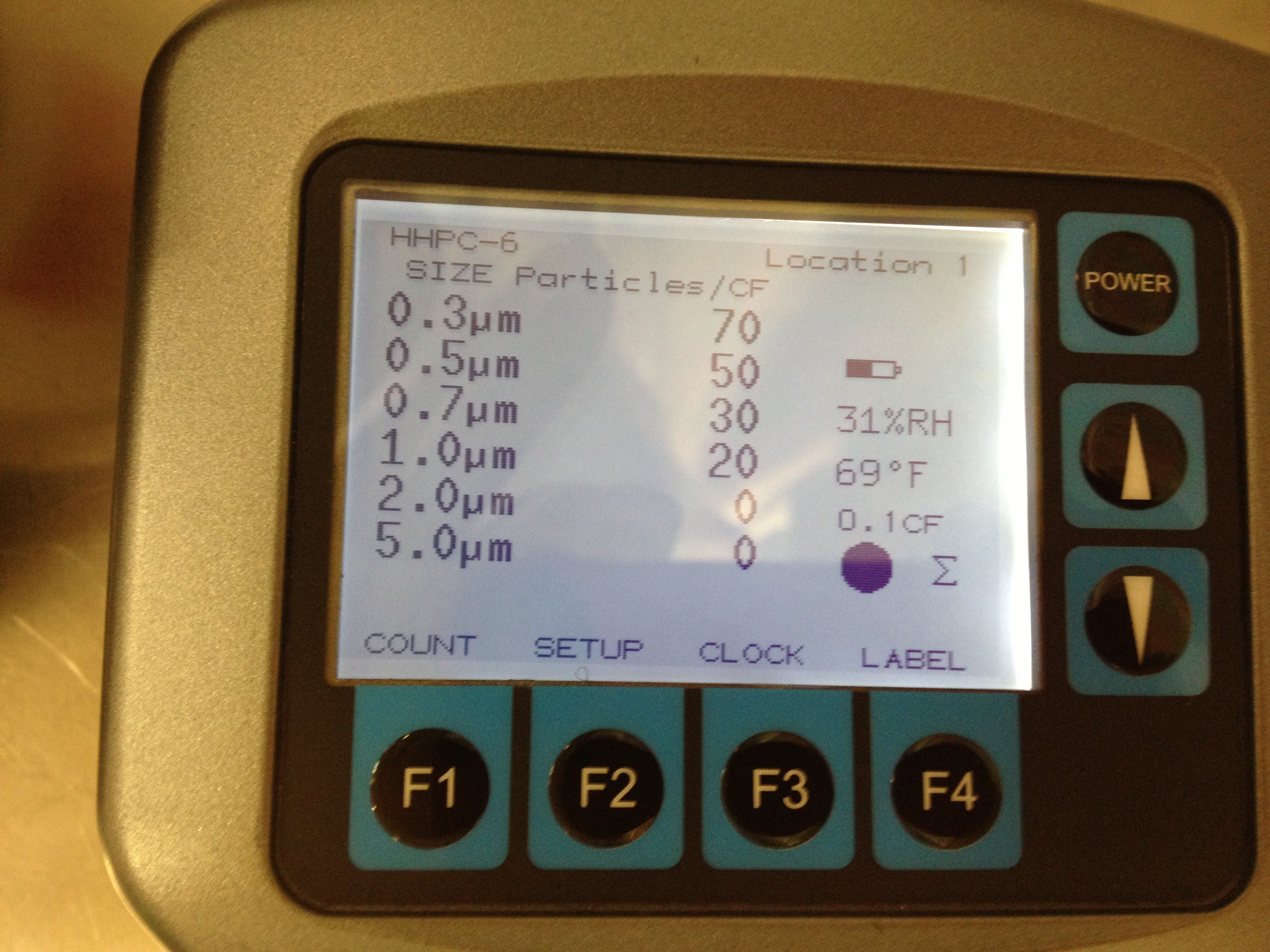
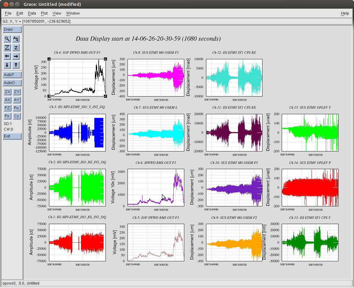
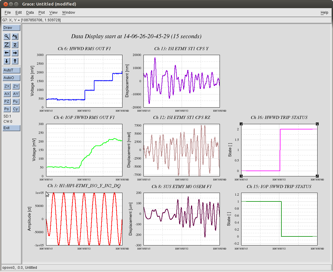
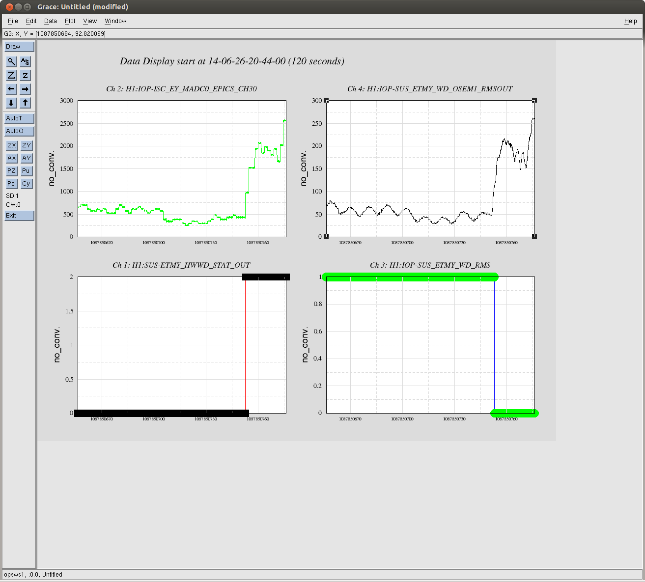
In the spirit of LHO aLOG 9204, we've shaken H1 SUS ETMY using H1 HPI ETMY in order to test the sanity of thresholds set for both the IOP Software WD (IOP SWWD) and the newly implemented Hardware Watchdog (HWWD). These values are currently set at 110 [mV] output of the RMS circuit (which is identical both in the HWWD and IOP SWWD), which via this test, is determined to be roughly 10 +/- 5 [um] or [urad] peak-to-peak (as reported by ISI ST1 CPS, SUS M0 OSEMs, and SUS L3 OPLEVs). See attached overall time-series of the entire test, whose timeline is below. This mount of motion has been blessed by my spider sense of "Wow, that's a *lot* of motion; it's giving me the willies. We should cut off SEI excitation after 10-20 minutes of this." Note that, gauging by the motion of speed-dials, this amount of motion is still *less* than what occurs if, say, Betsy and Travis are mechanically aligning the suspension, so it's still a conservative threshold (because, of course, when at vacuum, and the chamber is fully isolated no such motion should ever occur).
Things we've learned:
- The IOP SWWD and HWWD now have their threshold set to 110 [mV], equivalent to ~10 [um] or ~10 [urad] of motion, pk to pk.
- The RMS output of both the IOP SWWD and HWWD track each other quite well -- as long as the signal is above ~30 [mV] or ~3 [um] or [urad] -- only the IOP SWWD readout is more the accurate below these amplitudes.
- Driving a 0.1-to-10-[Hz]-band-limited, white noise excitation at he maximum amplitude of HEPI's DACs does not trip the IOP or HW WDs. One must focus the power at a given frequency to really ring up the RMS.
- The calibration from counts to mV for the HWWD RMS OUT channel -- for now, randomly stuck in H1:IOP-ISC_EY_MADC0_EPICS_CH30 -- is roughly 0.1 [mV/ct].
Why the HWWD user interface is icky, but it'll still work:
- (As mentioned above) the RMS output of the HWWD does not report any change unless there is a significant amount of motion already present.
- The RMS output of the HWWD is choppy -- performing a sample and hold on the RMS value, and jumps around by 10s of [ct], or a few [mV] under constant excitations.
- The three HWWD analog trip flag channels -- for now, stuck in H1:IOP-ISC_EY_MADC0_EPICS_CH27 through 29 -- are railed when not tripped, and low when tripped.
- The after entering value in the requested RMS voltage trip point, H1:SUS-ETMY_HWWD_RMS_REQ, the readback, H1:SUS-ETMY_HWWD_RMS_RD only returns a value *close* to what's been requested. Similarly the two readbacks, H1:SUS-ETMY_HWWD_TIME_RD and H1:SUS-ETMY_HWWD_TTF_SEI for the time until trip report values only *close* to the requested value, H1:SUS-ETMY_HWWD_TIME_REQ.
There's still a significant amount of hardware that needs installing / replacing before we can hook the HWWD up to actually kill ISI coil drivers and HEPI valve drivers, but we will now propogate these thresholds and this infrastructure to the remaining QUAD suspensions over the next week or so. We will also perform a similar test on HAM chambers once they become available, to set those SUS' IOP SWWD thresholds (or at least confirm that they should be the same.)
Detailed Time Line
GPS Time Amplitude Notes
1087849965 100000 WN; Y, RX, RZ
1087850060 200000 WN; Y, RX, RZ
1087850199 250000 WN; Y, RX, RZ
1087850287 400000 WN; Y, RX, RZ
1087850326 HPI USER WD Trip
1087850348 start over
1087850484 300000 WN; Y, RX, RZ
1087850742 300000 WN RZ RX; 100000 ct 0.5 [Hz] Sine Y
1087850995 done
1087854054 Full bandwidth HEPI TF
where WN = white noise excitation, between 0.1 and 10 [Hz], and 0.5 [Hz] Sine = single frequency sine wave at 0.5 [Hz].
As in the original test, I turned OFF all control on the ISI and SUS, and turned OFF isolation control on HEPI. When ramping up the test, I began driving HEPI without turning off the ISI -- the ISI isolation loops survived through 20000 [ct] of HEPI excitation.