Kiwamu, Stefan, Lisa
After talking with our LLO locking friends, spending some more time trying to further reduce the CARM offset, and thanks to the fact that tonight everything else was working fine, we think we know why our CARM offset reduction is so painful.
At LLO, the transition to 3f signals can be done with a very large offset (~ 3kHz), and once the transition to 3f signals is done, there is no particular issue in reducing the CARM offset down; no adjustments are done in the DRMI control.
Here, first of all we can transition to 3f signals for PRMI only after having passed the 18 MHz resonance in the arms (~970 Hz). This implies using the REFL 45 I&Q signal down to 700-800 Hz, which can be done only by tuning the demod phase on-the-fly .
Second, once on 3f, without constantly tuning the MICH loop (gain, offset, demod phase), we can't keep the PRMI locked while reducing the CARM offset.
We realized that the problem is that here we are using REFL 27 Q for controlling MICH, instead of REFL 135 Q. This is bad because REFL 27 Q is much more sensitive to the CARM offset, and offset and gain changes for this signal are indeed predicted by Kiwamu and Anamaria's simulation (though we don't have on hand plots for the exact CARM offsets we are currently at; Kiwamu is in the process of producing more plots).
The reason why historically REFL 135 Q was not used here is that there was essentially no signal. By comparing the LLO parameters with the ones we are currently using, it looks like we should increase the modulation index by at least a factor 2 and increase the light on the BBPD.
On the other hand, once we realized what was going on, we could reduce the CARM offset down to 250 Hz, by keeping the MICH loop happy monitoring offset, gain, and demod phase, and adjust all these parameters by hand. We could probably keep going, but there is no much point in doing that if we believe that we are just making our life harder by using a hostile signal.
Here is the roadmap to reach 250 Hz:
CARM OFFSET / MICH OFFSET
700 Hz / +200 cts
600 Hz / +400 cts
550 Hz / +800 cts
400 Hz / +900 cts
350 Hz / +900 cts
250 Hz / +1300 cts (PRCL offset -1000 cts)
MICH GAIN = 2
PRCL GAIN = 1.5
Other changes we did tonight:
1. Stefan relaigned the full IFO (X arm green, X arm red, TMSY single shot to beat note, Y arm green, PRMI)
2. We added a notch in the PRCL loop for the 70 Hz periscope resonance
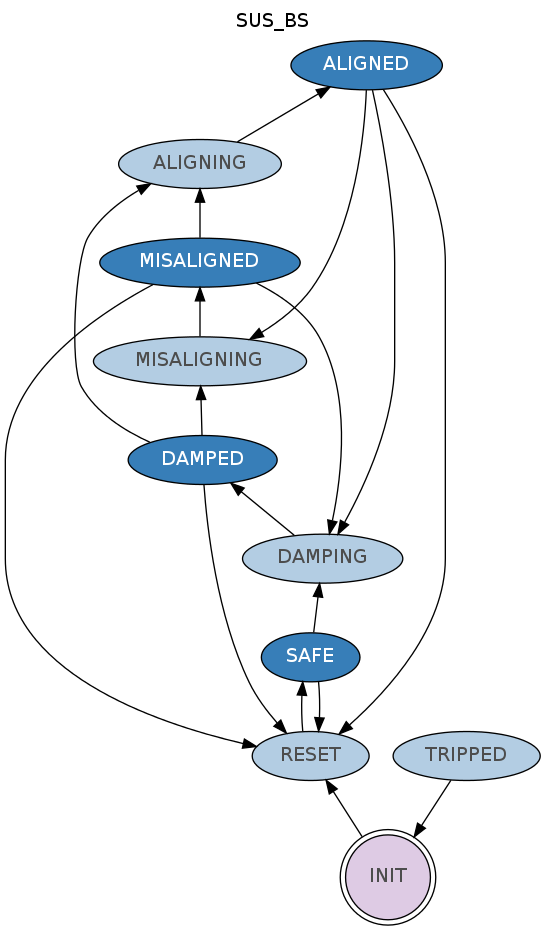
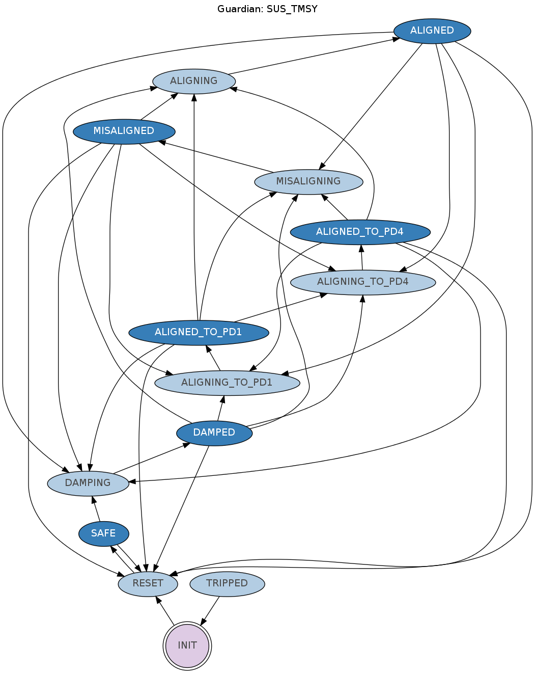
3. We realized that theTMSY YAW damping loop has been off since May 15.. we re-closed the damping..
4. We modified the ALS slow path to include a 40 dB 5 second ramp for smooth engaging
5. We re-commissioned the Y arm ITM dither alingment loops, 1 dof only, in PITCH and YAW (the PZT loops are broken for both arms since the WFS software upgrade)

This is how the magnet looked in the UR M2 AOSEM before bracket "attitude adjustment".
This is the bracket-AOSEM mechanical intereference that didn't work today. (Note, we've reported that on many of our HSTS suspensions at LHO these brackets are at the end of their range, it just bit us this time. I do not know why they are all high at this stage, but the suspension pendulum modes match the model so the pendulum lengths are correct. Our last round of diagnosis on this many months ago was hand washed off that the LHO suspension structures were possibly from a different batch than the LLO ones and therefore there is a mechanical difference in how these AOSEMs are mounted.)
And this is the bracket with my hand-crafted AOSEM relief shape which shoulda been in the bracket in the first place.