Summary:
OM2 was rebalanced, but one of the BOSEMs is bad (one of the PD pin is grounded to the tip tilt body). We will replace it with a spare tomorrow.
We found that the shielding of QPD sled picomotor cablesand WFSA DC cable were grounded to the ISI. The former was fixed by loosening the DB25 connector mating screws and pulling the DB25 back a bit. The latter was fixed by loosening an ultra-tight cable clamp at the stage zero of the ISI.
Please do never tighten the cable clamps so hard that the cable cannot move. You should be able to move the cable through the clamp by pulling gently, though the cables should stay in place by friction when left alone.
Details:
I pulled the OM2, rebalanced, installed again, made sure that BOSEM flags don't interfere, set the BOSEM depth, and THEN found that some of the ground loops were back, and one of them was of course OM2 itself (not the cable).
Pulled OM2 again, and it turns out that the coil with a tiny gap that was OK before was touching, causing the grounding issue. By pushing or pulling the connector using my finger, I was able to make or break the connection, and when I remove my pressure it didn't go back to the original state.
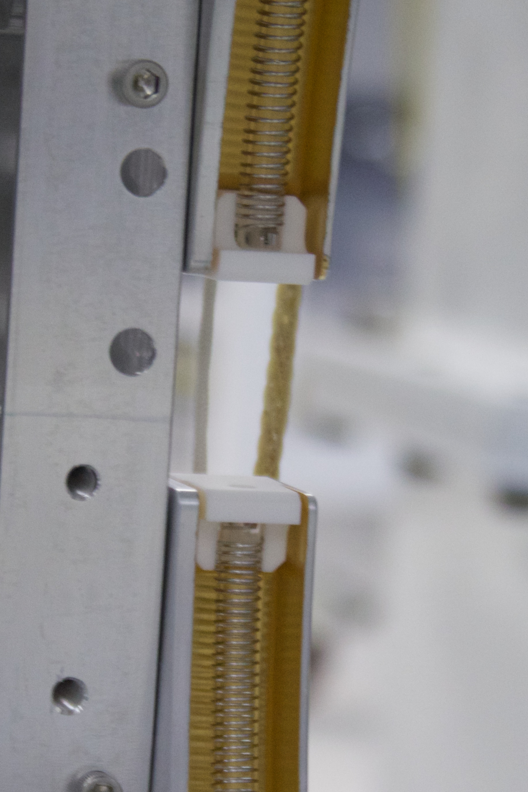
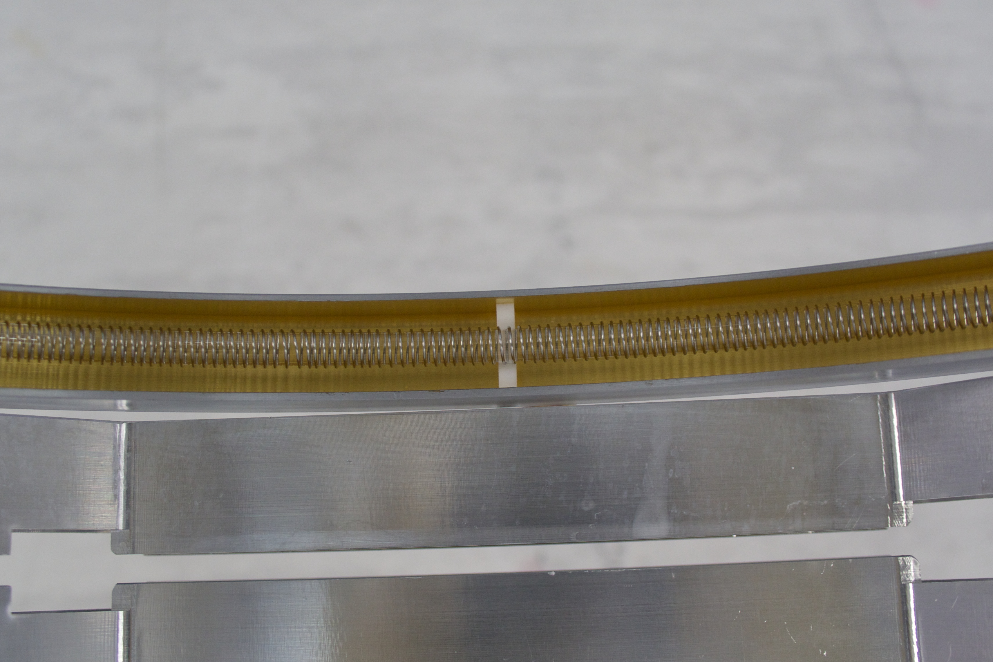
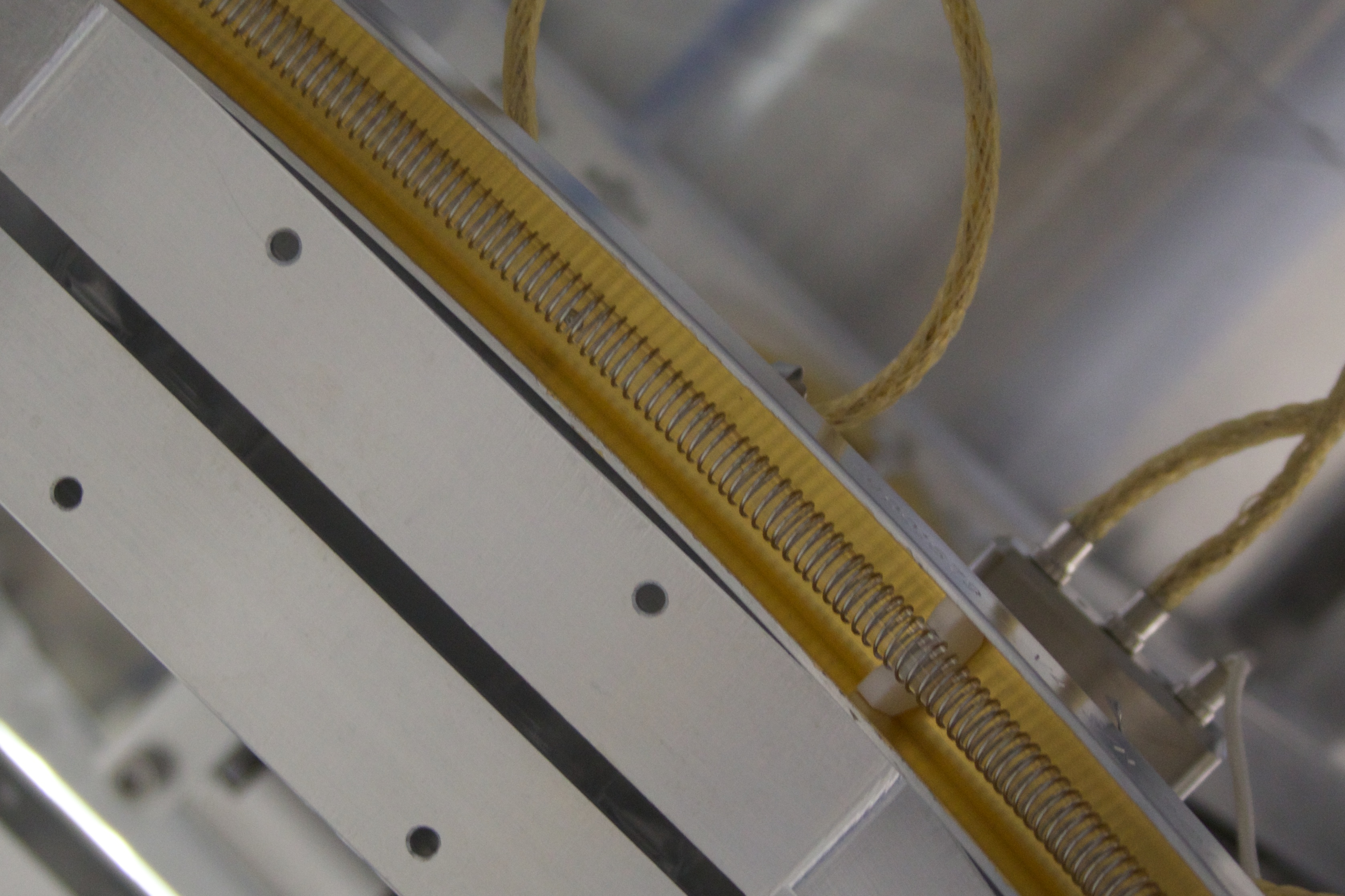
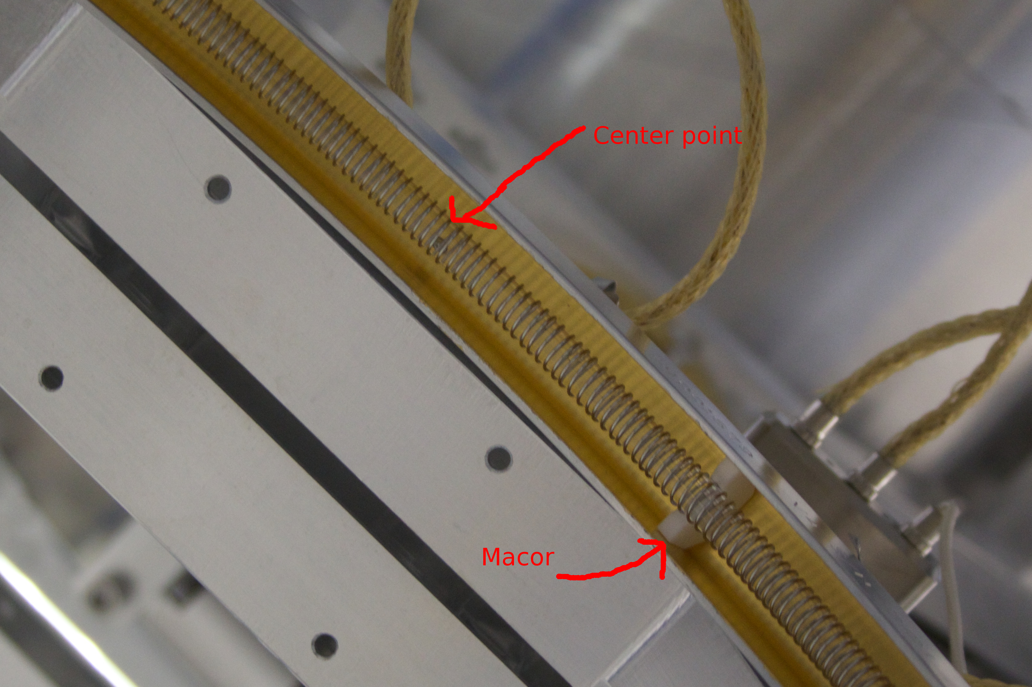
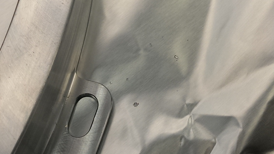
I applied aluminum foil as a shim between the coil bobbin and the connector to make the bottom gap larger, and cocked the connector more to make the side gap larger (I needed to make one of the mating screws somewhat looser than the other), so that there is a clear visible gap all around the metal shell of the connector. It was tested good on the work table, so we installed it back to the table.
When we started setting the depth of the BOSEMs, UL coil was stuck at -8000 or so counts (it was not in the morning, but Dan recalls that that coil was stuck at that value on Friday).
I pulled the coil out while keeping the electric connection intact, and as soon as the coil came out suddenly the open value was -32k counts. As soon as the coil touches the ISI surface, it went back to -8000 counts.
It turns out that one of the pins for the PD for the BOSEM is short circuited to the coil bobbin, and of course the coil bobbin is grounded to the tip-tilt frame. In the morning, for some magical reason, it should have been that the PD pin was not short circuited, or the coil is not grounded to the tip-tilt frame.
Anyway, this is clearly a bad part, and we need to replace it with a spare.
Also UR coil open voltage is somewhat small (-20000 cts), so we'll see if replacing this BOSEM changes it.
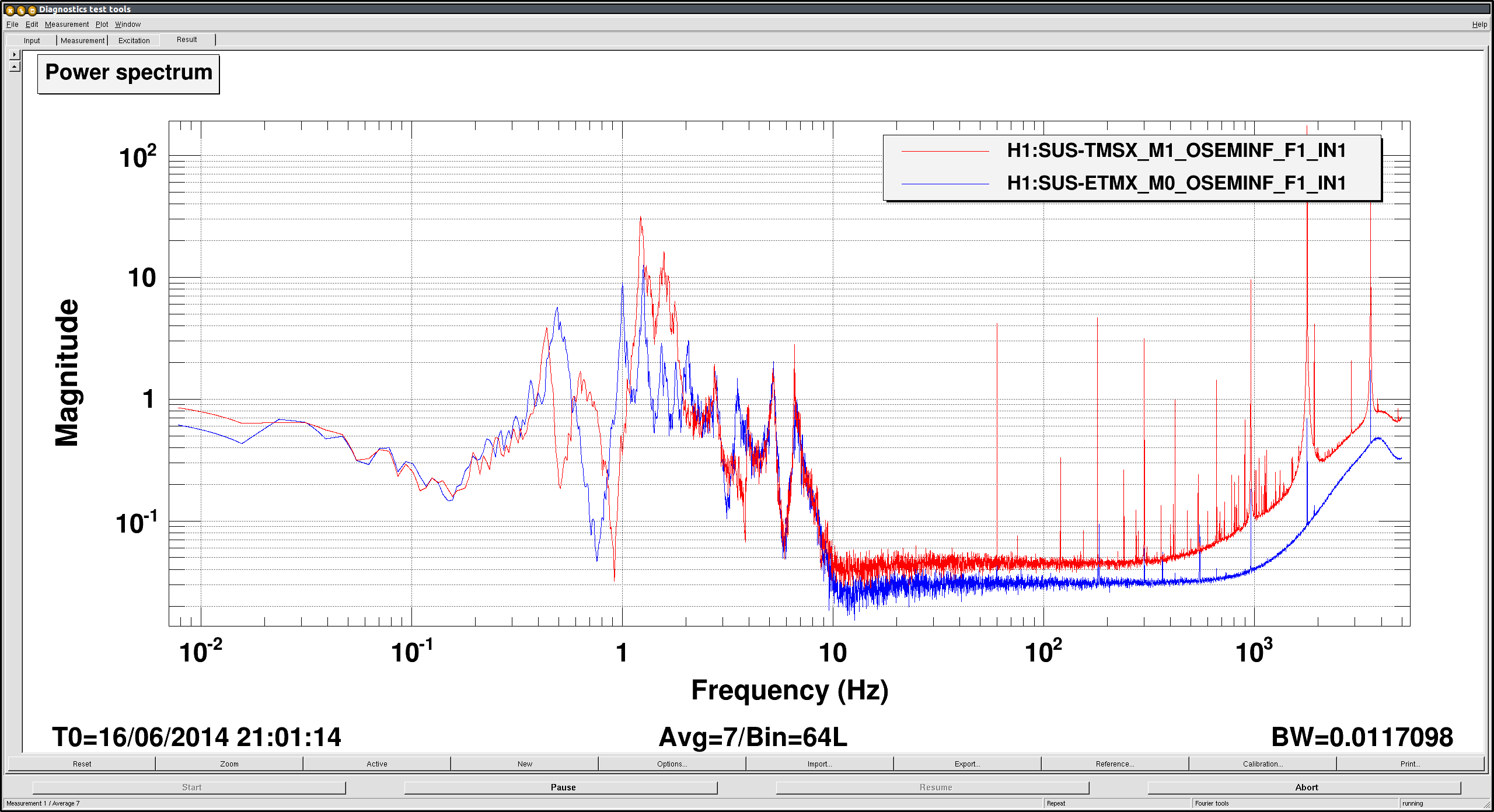
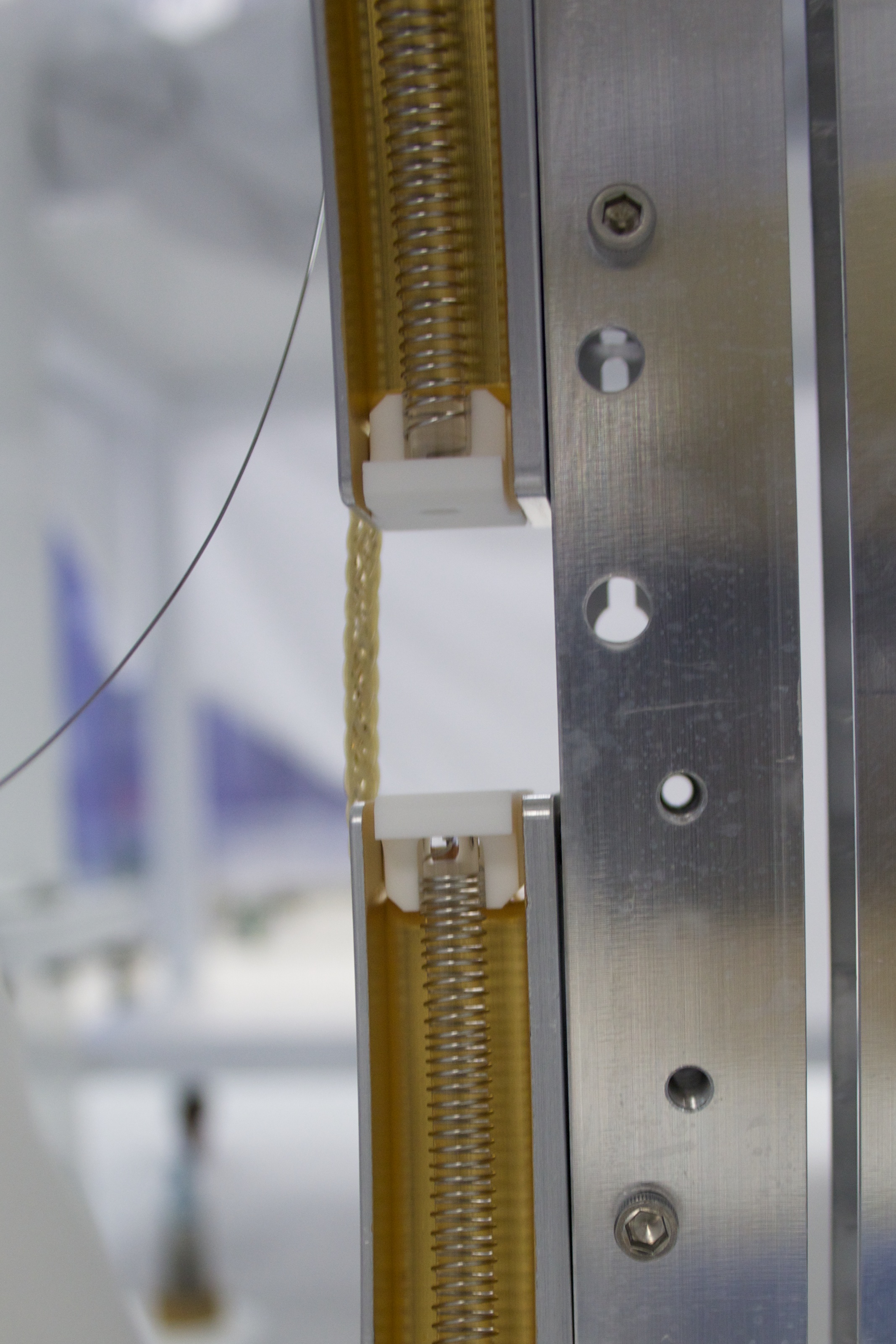

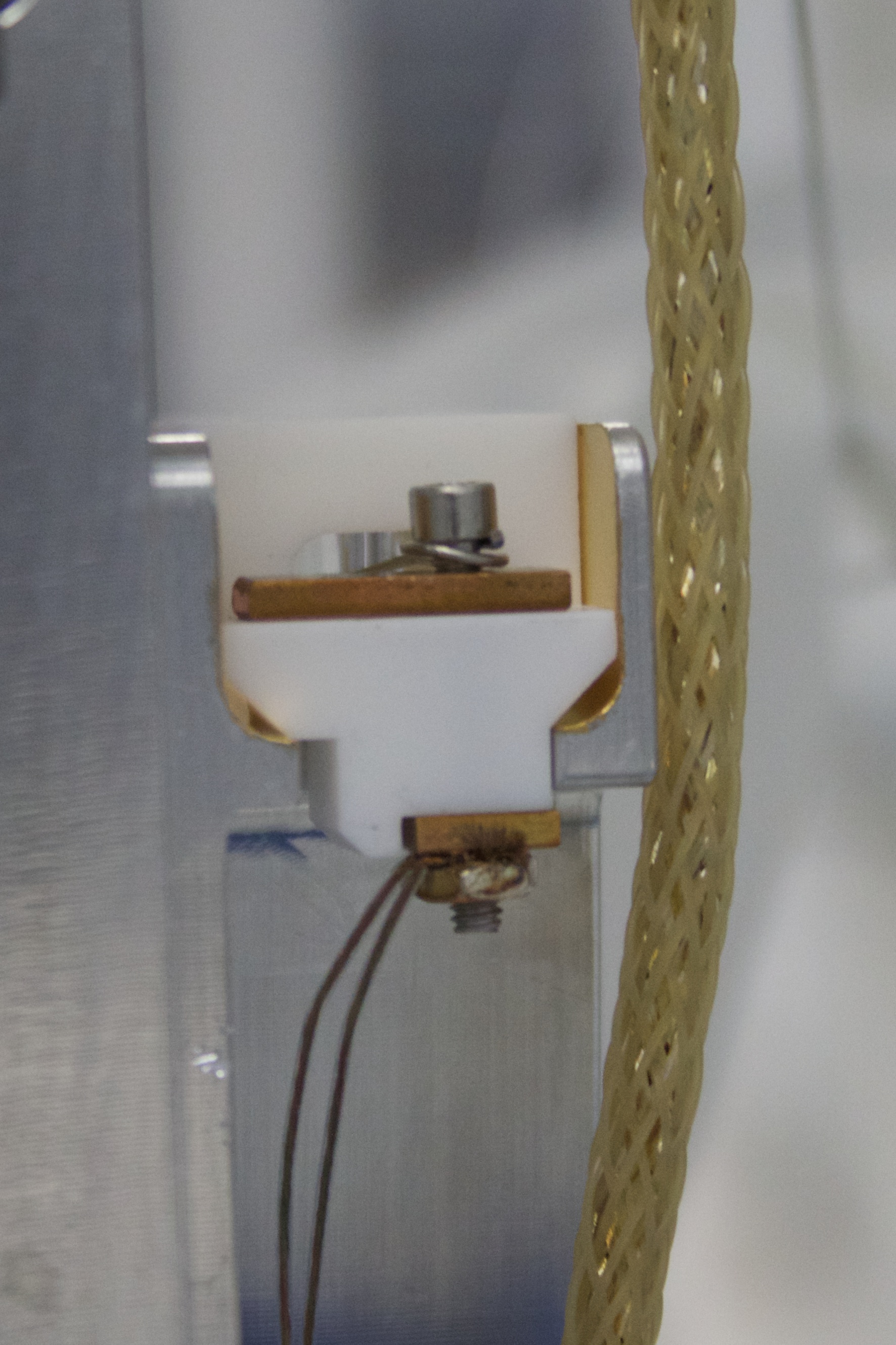
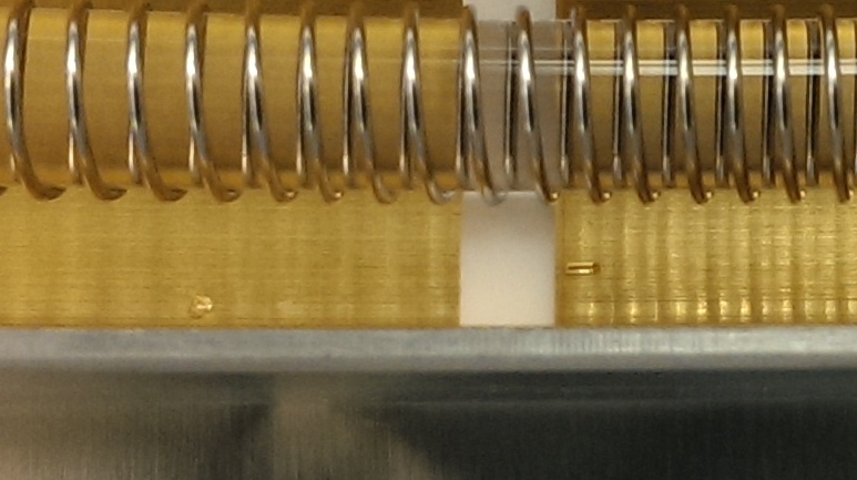
Attached is a picture incdicating which connection on the BOSEM is shorted to the body. According to T060233, it's one of the pins on the photodiode (which has the round hole; the IRLED has the slit, inside the BOSEM body). With the BOSEM removed from the TT assembly we were able to use an allen key as a flag to block the shadow sensor and see some variation in the signal. With the BOSEM touching a conductive surface the signal is stuck at about -6800 counts. (Thanks to Keita's careful shimming, the cable connector shield is not electrically connected to the body of the BOSEM.)