(Aidan B, David H, Thomas V, Alastair H, Matt H)
(Note this is talking about TCSx table)
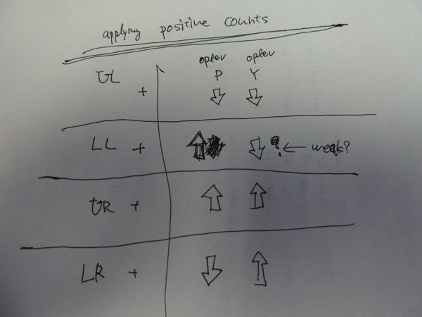
So finally some success. The first polariser after the laser was moved from before the AOM to after the AOM (and positioned such that the transmitted beam from the AOM goes through the polariser but the first order beam does not). It was then quite easy to alter the polarisers so that I got a minimum power reflected of off the 2nd polariser after the Beckhoff controlled HWP of 4.5 mW when in CW mode (HWP setting of 36.4 degrees gave this maximum power). The power transmitted onto the high power, power meter was 44W. (see top drawing on attachment).
We now can begin aligning in earnest again. However as we want to start running the laser around the clock soon, we started putting some other provisions in place first.
-
The manifold was modified so that we could use the water cooled beam dump and the water cooled beam dump is now positioned after the first polariser after the HWP, so we can now dump all the power there as designed.
-
One of the quadrant thermopiles has been placed on an x,y, z, translation stage so we can start calibrating these quadrant thermopiles
-
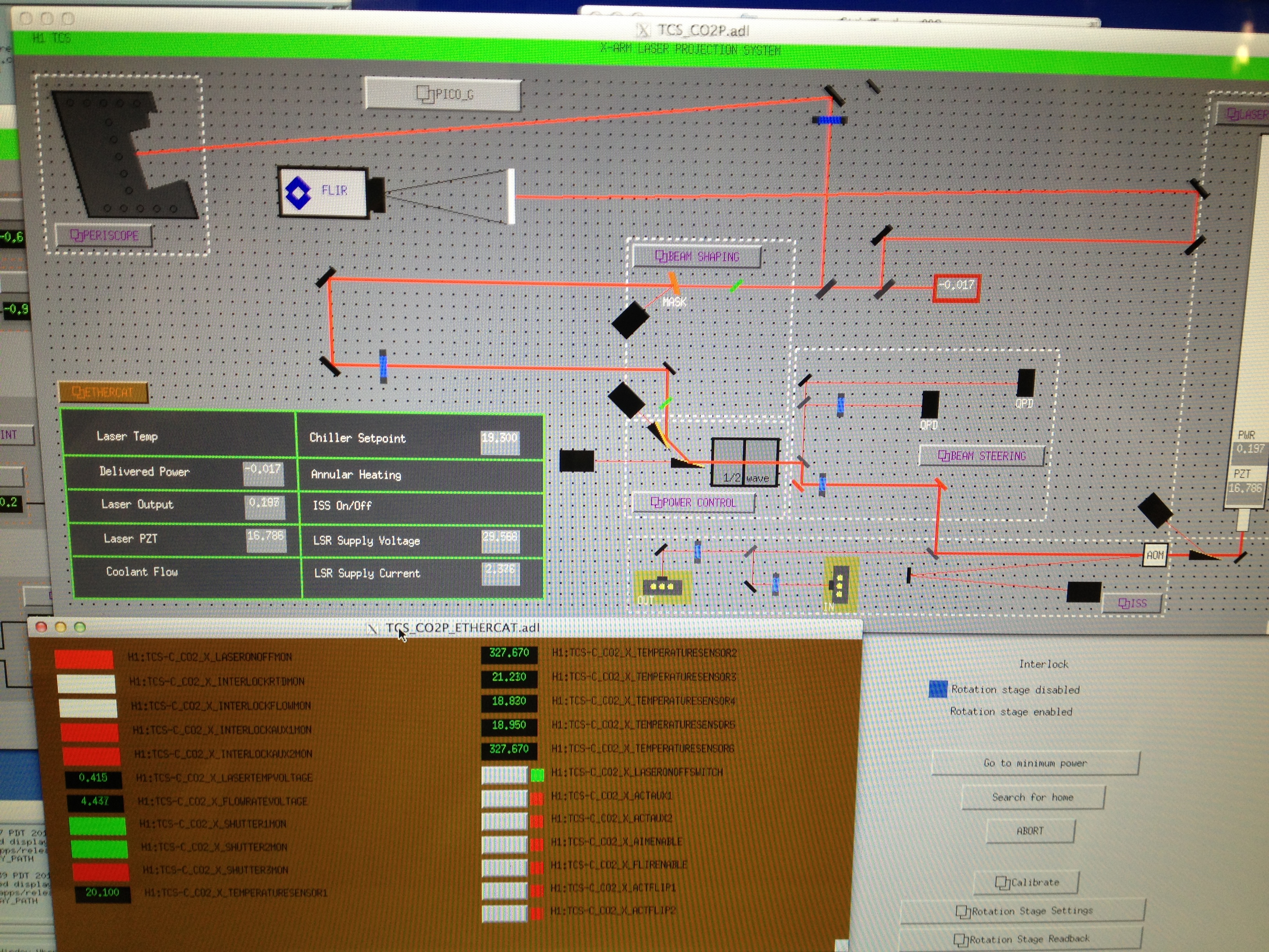
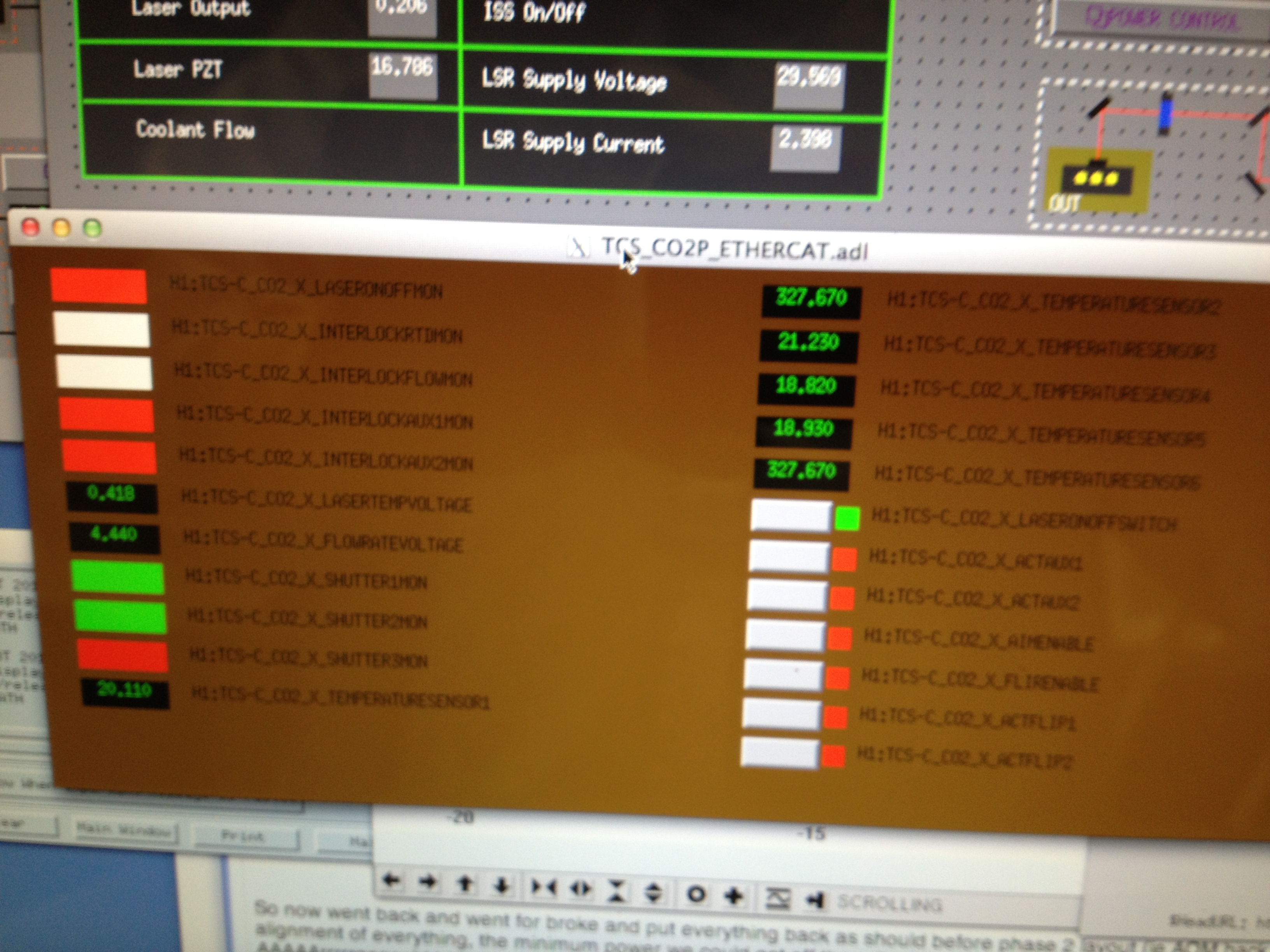
Temperature sensors were placed on the AOM, AOM drive, RF drive and the water cooled beam dump. One will also go on the manifold also once I get a bracket modified to hold the thermistor in place. To see these temperatures go to the main CO2 screen, click on the ethercat tab and you will see 6 temperature sensors (see pic 1 and pic 2). Temp sensor 1 is the AOM, Temp senosr 2 will be the manifold (not plugged in yet), Temp sensor 3 is the AOM drive, Temp sensor 4 is the water cooled beam dump, temp sensor 5 is the RF drive and Temp sensor 6 is a spare (not plugged in). I have asked that these be relabelled with something sensible (apparently names are generted in Beckhoff).
-
We have started putting up laser barrier shields at the edge of the table near the laser
I also was going to put in the PD's that will be used for the Intensity stabilisation as they arrived today. However they dont physically fit. So we are going to have to come up with a different layout. Aidan is currently looking at what we will do. We also tried to put a breaker box supplied by Ben Abbott between the ISS box and the feedthrough. We had some issues with the connectors at the feedthrough working so we reverted back to the old setup. David was modifying so that we can try again tomorrow to connect this up
We have continued aligning after the polarisers and now have the 1st flipper mirror, lens and 2" steering mirror aligned. I thought this to be a good stopping point for the night as I am confident I can get the rest aligned tomorrow now. I have put a beam dump after this mirror to dump the beam into, so the laser can be started up at any stage if I am not here and all beams should be dumped. (see second drawing in attachment of sketch what done thus far).The Beckhoff controlled HWP has also been set to 36.4 degrees and so should dump the majority of the power into the water cooled beam dump.
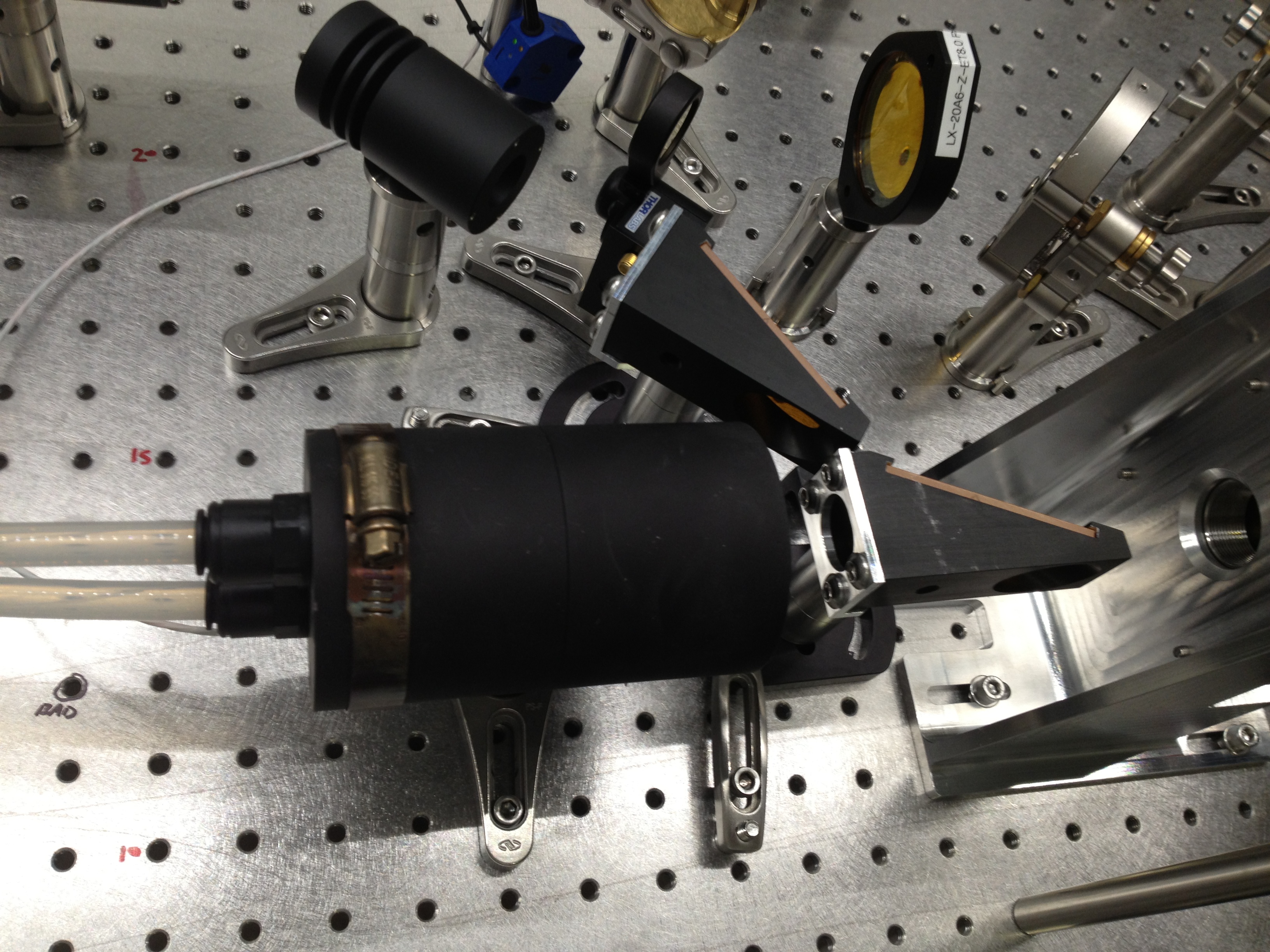
Pic 3 shows the table layout as currently done
Pic 4 the water cooled beam dump (note hose clamp holds temperature sensor in place)