J. Kissel, L. Barsotti, D. Hoak
Hoping to make a measurement of the length actuation force coefficient for the ETMY ESD, we tried to lock the Y-Arm using ALS. We've failed, and we don't know why. Below I outline our debugging process, but it's really not that interesting since we never found a culprit. Our best guess is something wrong with in analog at the Y-End PDH demodulator's local oscillator, because
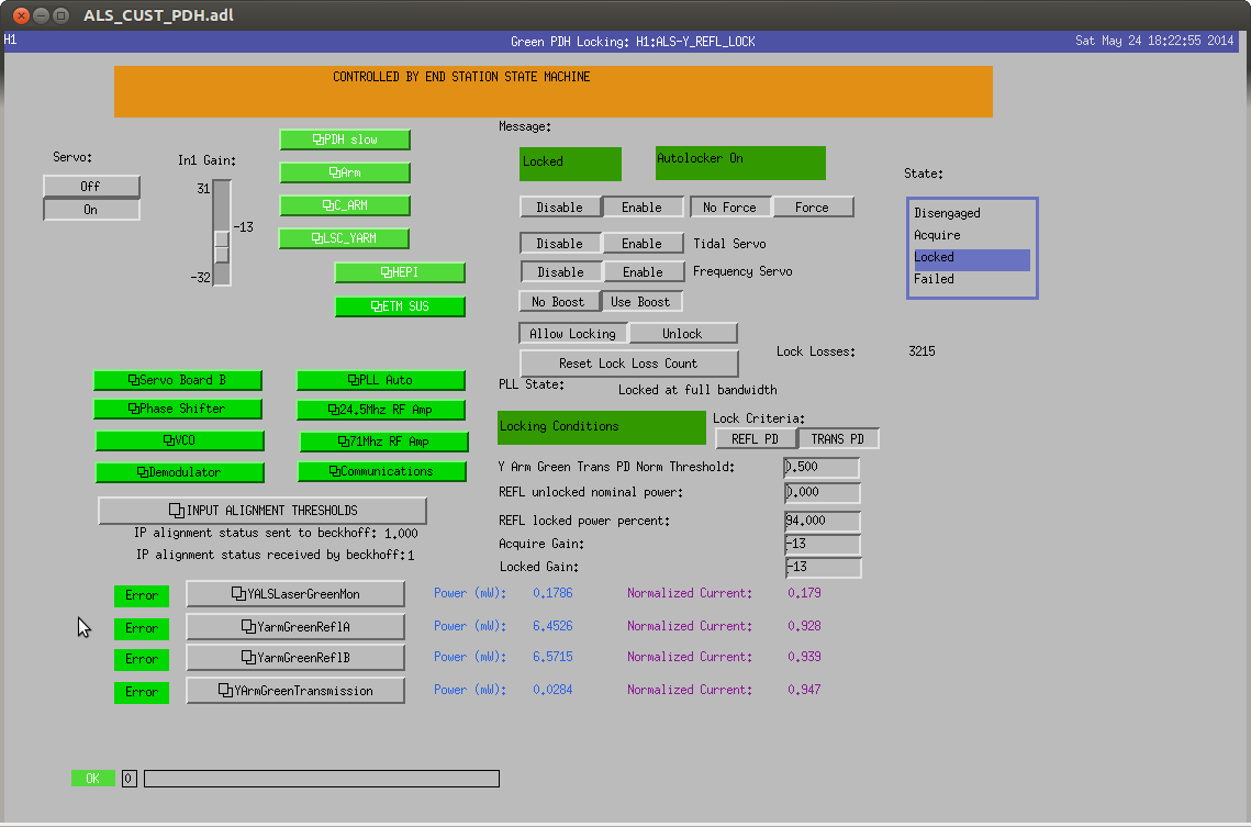
- when we request the Guardian to changed to "LOCKED_NO_SLOW," it immediately faults out with a rather unhelpful "PDH" error message.
- H1:ALS-Y_REFL_LOCK_ERROR_MSG on the PDH overview screen claims "demodulator"
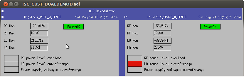
- DEMODs complain of an error message "LO power level out-of-range" for both the "REFL" and "SPARE," where the nominal values are 20 and 22 [??], respectively and the monitored values show ~ 21.2 and ~ -36.9 [??]. Dunno what units these are in. Maybe dBm?
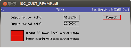
- Opening the 71 MHz RF AMP screen, there are errors shown "Output RF power level out-of-range" and "Power supply voltages out-of-range" with a nominal value of 20.5 [dBm], and a monitor value of 51.9 [dBm].
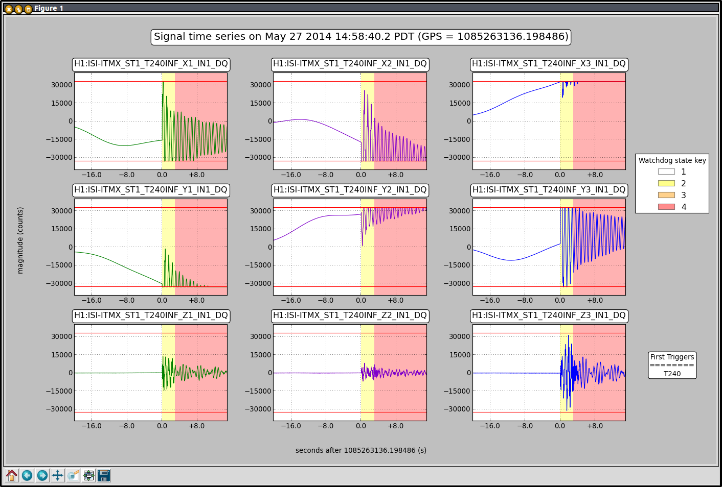
X-Arm remains happily locked, and even survived a the big earthquake that took out the Y-ARM.
Merp.
- Found no light or flashes on ALS Y GIG-E camera monitoring the transmitted light.
- Found all Y-arm ISIs tripped (probably because of an earthquake -13 hours ago, but strange that it didn't affect X-arm. Did look that hard.)
- Found ISI subordinate Guardians not responsive because a ca.get request for the master switch had faulted out.
- Reloaded all sub-ordinate Guardians, restored them in managed mode
- Reset Y-arm ISI watchdogs. Erred out because it "filters are not in expected stated," or something like that.
- Reloaded manager, switched requested state to OFFLINE to start everyone over
- Reloaded subordinates again, set to managed, requested FULLY_ISOLATED, and things came up -- slowly, but surely -- included HEPI realignment.
- Found SUS ITMY PUM WD tripped, which forced Guardian to go to safe, with the master switch OFF, and therefore no alignment biases.
- Reset SUS ITMY WD, waited for guardian to turn everything back on. As soon as alignment sliders came on, we began to get transmission flashes on the GIG-E camera.
Since flashes, we've gotten no where. As mentioned above, the ALSY Guardian immediately faults.
- Tried tweaking alignment, because we thought transmission flashes were below locking trigger threshold. Tweaked up alignment, got normalized transmission up past 1.0, still no dice.
- Looked at optical levers after ISIs settled, there's slightly higher motion than the X-ARM, but nothing outrageous -- at MOST 0.2 [urad]_{pkpk} in ITMY, but I think that's because the blend filter configuration is different between ETMY and ITMY chambers.
- The state machine is preventing us from changing any of the PDH Board configurations, but we find
- Both ALSY PDH inputs disabled -- maybe because Guardian's waiting for "PDH" to be OK?
- Error point, H1:ALS-Y_REFL_ERR_INMON shows identically zero signal.
- DEMODs complain of an error message "LO power level out-of-range" for both the "REFL" and "SPARE," where the nominal values are 20 and 22 [??], respectively and the monitored values show ~ 21.2 and ~ -36.9 [??]. Dunno what units these are in. Maybe dBm?
- Opening the F AMP screen, there are errors shown "Output RF power level out-of-range" and "Power supply voltages out-of-range" with a nominal value of 20.5 [dBm], and a monitor value of 51.9 [dBm].
- H1:ALS-Y_REFL_LOCK_ERROR_MSG on the PDH overview screen claims "demodulator"
- Similarly (but I guess less important), there are some errors in the Phase-Frequency Discriminator spare (sign wrong, and LO out of range), but I think (a) the spares don't matter, and (b) the nominal values haven't been set.
#yakshaving