andres.ramirez@LIGO.ORG - posted 16:01, Thursday 15 May 2014 - last comment - 19:26, Thursday 15 May 2014(11921)
Ops Shift Summary
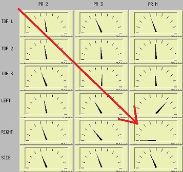
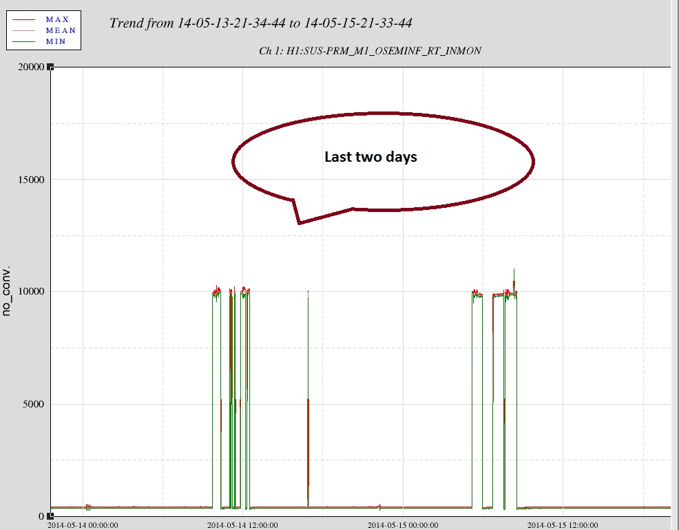
8:00-9:42 Getting ready to move clean room in LVEA (Craning) – Apollo
8:30 Water supplier on site – Paradise
8:35 Going into the LVEA to search for parts – Corey
8:40-14:00 Continue assembling/suspending/balancing of the ACB suspension- Betsy/Travis/Margot
8:48-13:02 Heading into the LVEA for SRM alignment – Jason
9:00-11:50 Joining Jason on SRM alignment – Jeff B
9:05-9:44 Retrieving items from LVEA - Gerardo
10:04-12:02 Heading in to the LVEA for TCSx table work – David
10:09-15:43 ICS rack inventory in LVEA – Filiberto
13:14 Restarting ISI model for ITMY – Dave/Fabrice
13:16 Restarting ASC model and the DAQ – Dave/Fabrice
13:32-14:20 Back to HAM5 to connect BOSEMs – Jeff B
14:05 Transitioning the LVEA to Laser HAZARD
14:13 Back to West bay (LVEA) – Betsy/Travis/Margot
14:37 Back to the LVEA for TCSY table work – David/Greg

 LVEA is Laser HAZARD!

NOTE: Today while going over the CDs Check sheet, I noticed that the Right BOSEM on PRM was reading almost 0. I talked to Alexa and concluded that it was because the suspension has been yawed.
Images attached to this report
Comments related to this report
Also, the flag of this osem seems to be a bit offcentered when the offsets are off (~ 100 um). We should recenter during next vent.

 The cookie cutters did their job and placed the suspension within spec for X, Y, and Z axis positions. The position errors are below: