(David H, Thomas V, Greg G, Alasitair H, Matt H)
Well if yesterday was "The Empire strikes back", today was "Return of the Jedi" and the good guys had a win.
You may remember from this mornings alog that we had been having a few troubles with the alignment of TCSx.
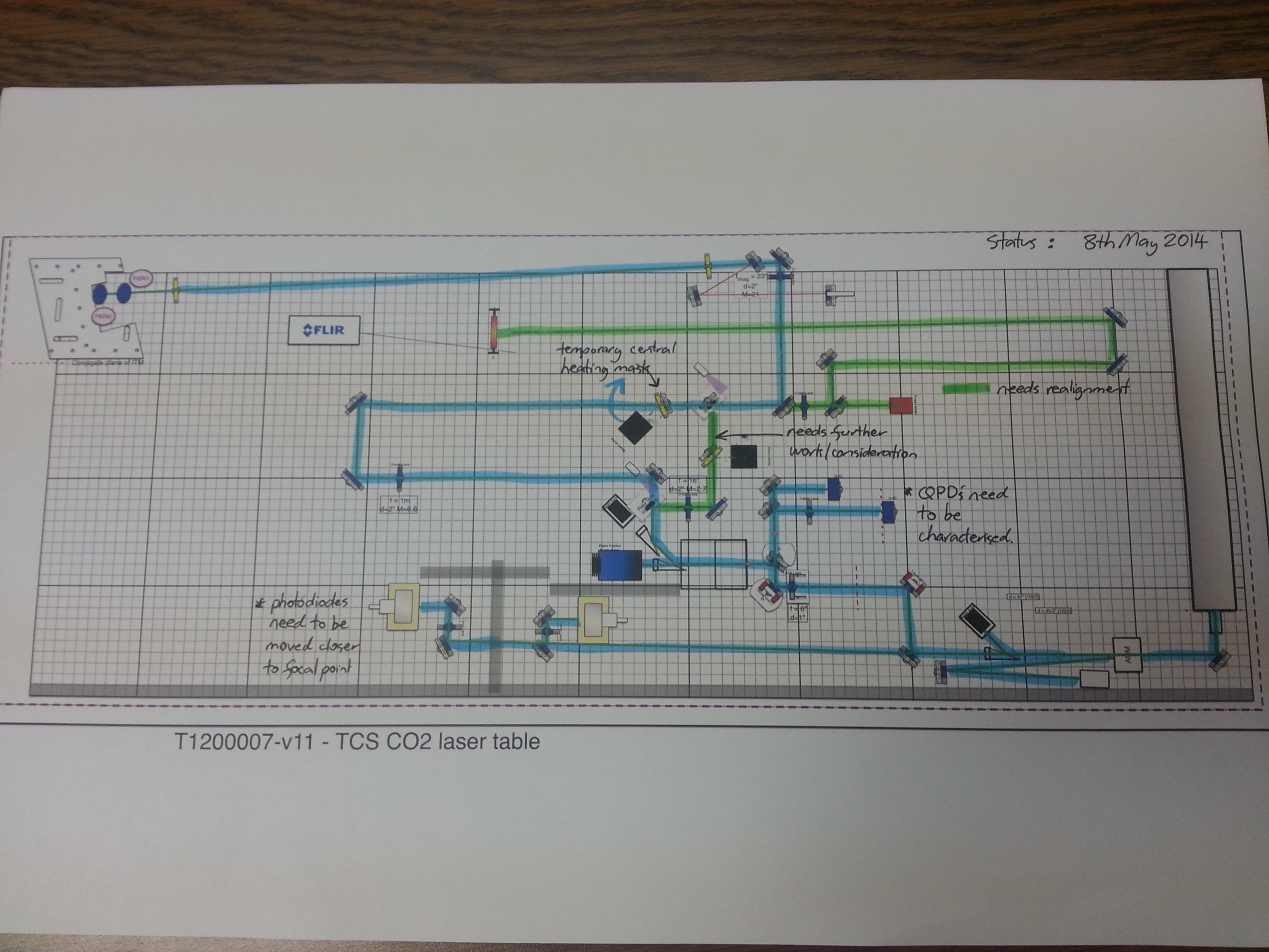
After a brainstorming meeting with Aidan the decision was made to ignore the path defined by the flipper mirrors having problems with (what is supposed to be the central heating path) and align what is the annular heating path (which only uses mirrors) to the output beam splitter and through the irises defining the beam path up the periscope, into the chamber and onto the CP. We will then use the central heating mask instead of the annular heating mask (in the location the annular heating mask would be ), and thus temporarily turn the annular heating beam path into the central heating beam path.
The first step we did was to use a HeNe beam to adjust the output beam splitter and the beamsplitter just before the on table power meter so that the front and back reflections were in the same plane (they werent installed that way). We then went all the way back to the first large gold mirror after the polarisers (which are after the beckhoff controlled HWP) and mirror by mirror in the annular (now temporary central heating) beam path made sure that they were set so that the beam was in a plane with the table at a height of 4 inches.
Once the beam got to the output beamsplittler, the beamsplitter and the last gold mirror before the periscope was used to align the beam to the irises that we had defined to put the beam correctly into the chamber. I roughly made sure that the beam transmitted through the output beam splitter was going to the on table power meter, and the beam path that would go to the FLIR camera was beam blocked as I no longer no that the beam path is correct (I removed the lens there so that needs to be reinstalled).
A HeNe beam was setup to trace through the irises (heading in direction of going towards the periscope). Once the optic beam path had been re-established I swapped out the 1" irises we had (which had clipping on the beam occuring) for 2" irises. We then inserted a 2 inch gold mirror into the path between the 2 irises and sent the HeNe beam down towards HAM5 and the target that we had set up at a distance that mimicks where the CP would be. An "X" was marked on the card and the HeNe aligned to this "X' and the FLIR camera setup so that this spot was centered on the camera.
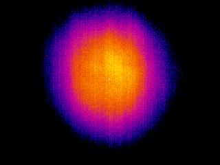
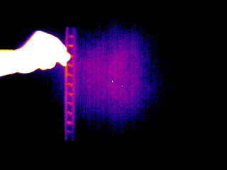
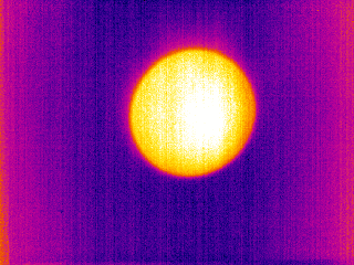
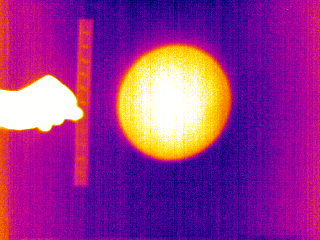
HeNe beam removed and the CO2 beam projected onto the target. Good to see that the CO2 beam appears to hit exaclty where the HeNe indicated it should (lets out sigh of relief)....so this should mean that the CO2 beam should go into the chamber and onto the CP correctly. Whilst doing the projection we also placed in the central heating mask (it has been rotated 90 degrees so that the rejected beam is directed towards the edge of the table not the center of the table as indicated in the drawing because the beam dump would not fit) and used the projection to help center the mask. Worked well...and success was declared. I dont have the pics of the projection, but pics were taken.
All beams have beam blocked so that if wanted to run the laser around the clock we can (we wont be until given the go ahead by the local LSO). A bugzilla list (Bug 868...https://services.ligo-wa.caltech.edu/integrationissues/show_bug.cgi?id=868) has been made of the tasks that can think of that are still outstanding/need to be done for this table.
One concern: A couple times today we had further issues with the HWP. We would dial up an angle for it to go to, the MEDM screens would indicae that the HWP was at the angle we had requested yet it physically was at a different angle. I have asked Thomas to look into tomorrow as this is a concern.
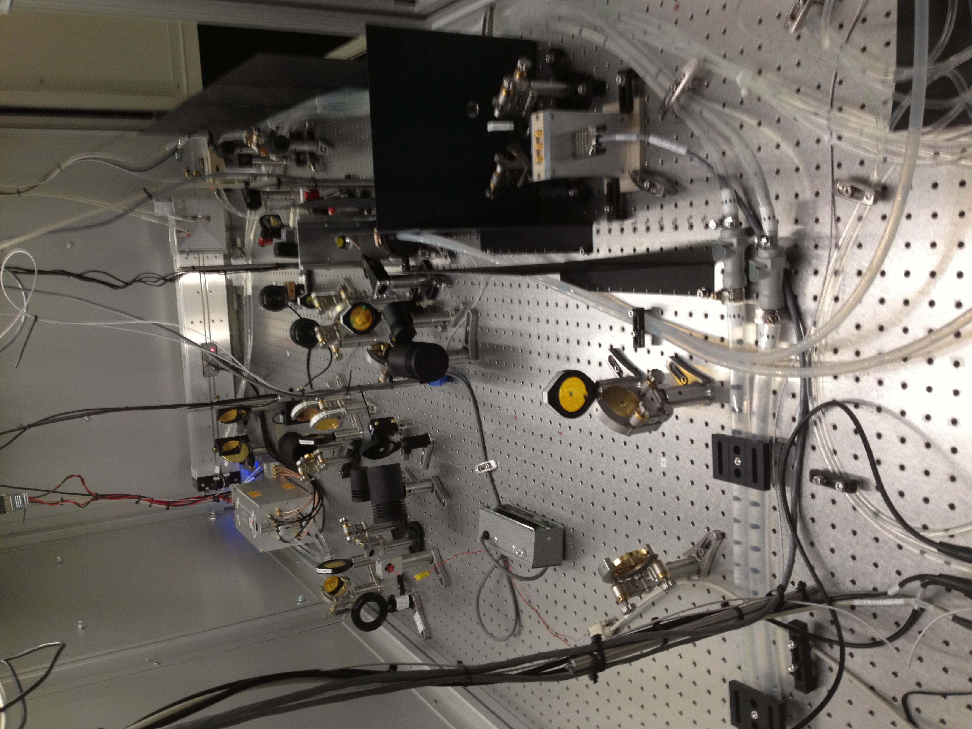
Pic:
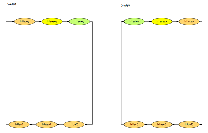
TCScurrentalignmentstanding shows a quick summary of whats aligned and what still needs to be done