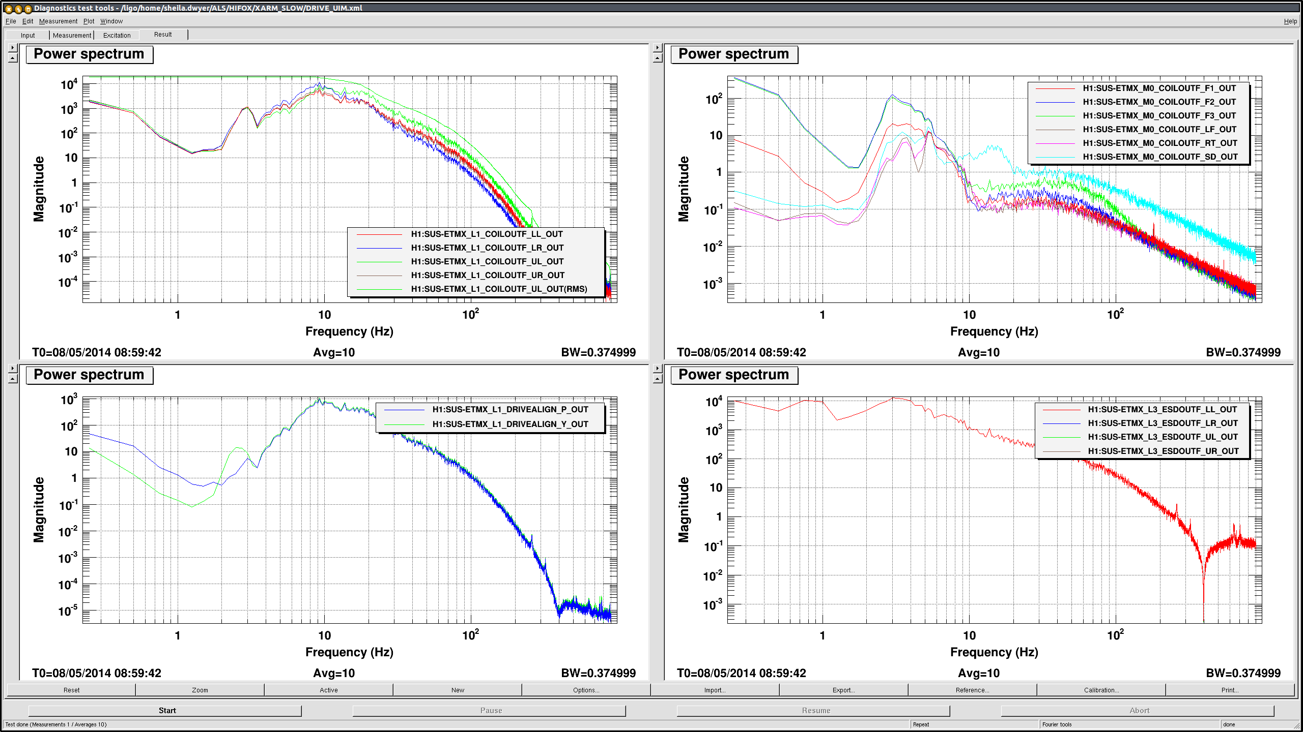
Since Stefan and Sheila weren't able to find the IR beam in ISCTEY the other day, I went there and looked inside BSC10 through the viewport.
The first thing was that the logic for open/close of the beam diverter is wrong AGAIN. When it's "closed" the beam comes to ISCTEY, when "open" the beam is cut by the beam diverter.
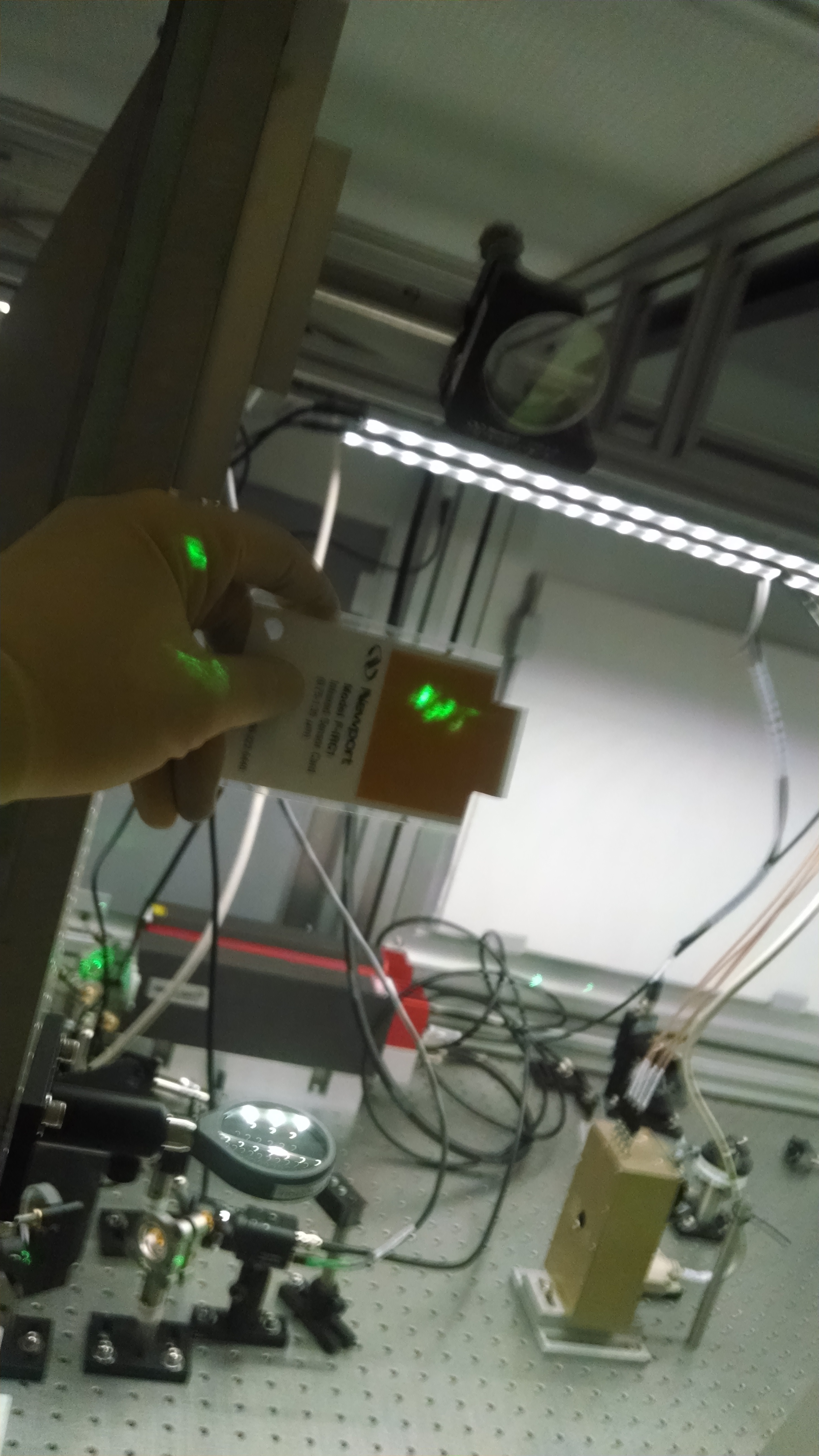
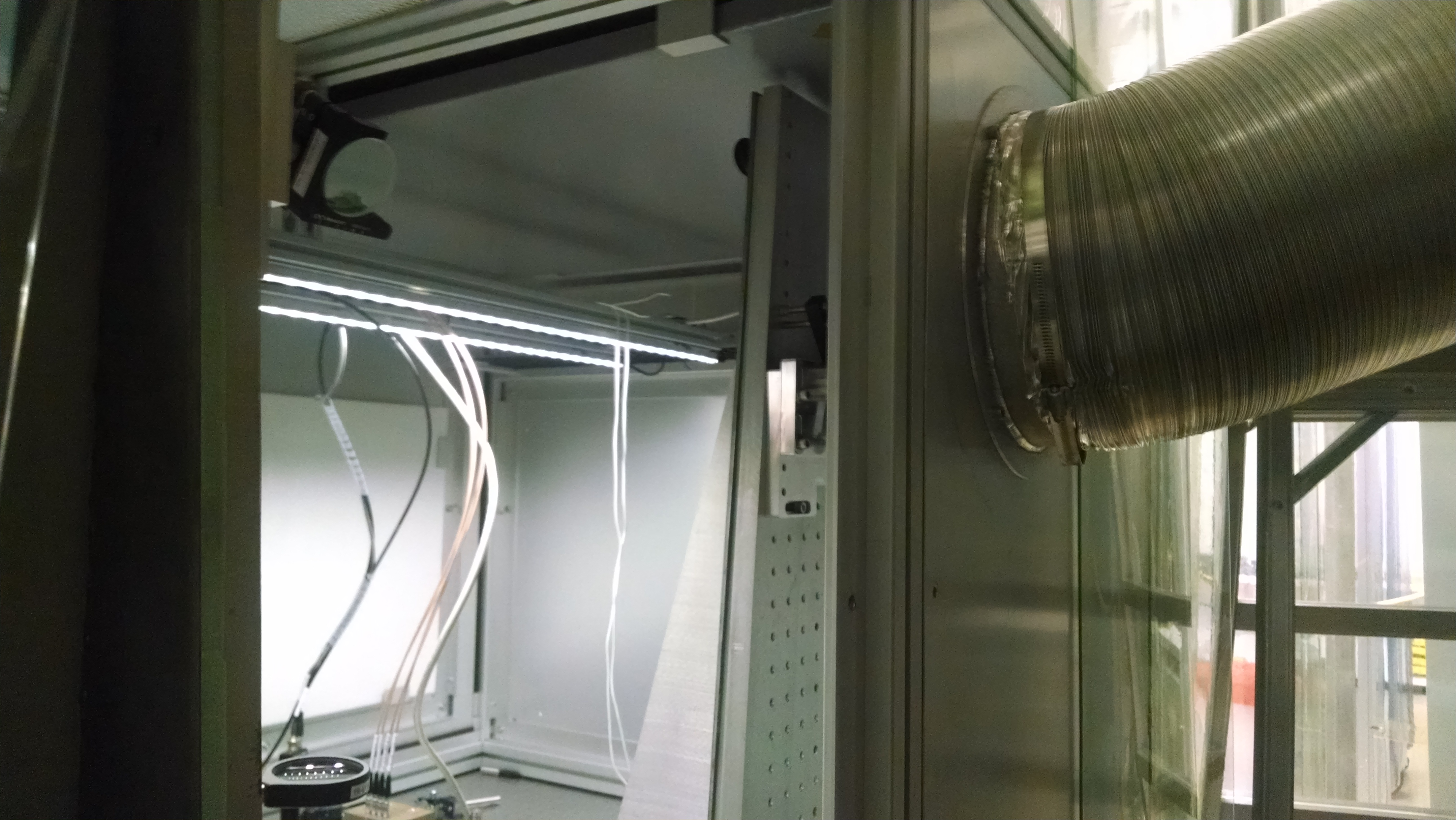
Second, I looked at the green beam retro reflected by ETMY leaking to the IR path, and was able to locate the beam in ISCTEY once the beam diverter state was set correctly ("closed"), but the beam passes about 6" below the periscope mirror (first picture) and hits the ISCT panel on the opposite side. We need to lower the periscope mirror by about 7". (Green leakage beam does not exactly follow the IR path because of the dispersion and the wedge of ETM, but it should be close enough to find the IR beam.) This could be done at any convenient time (maintenance, earthquake, ...).
Third, Aaron brought a good replacement cable for ISCTEY camera, we tested and it was good, but I didn't install it (I need to leave now), it's just sitting on the ISCTEY table. This camera is not useful until the periscope mirror is lowered anyway.
The second picture shows how high this periscope is as of now relative to the green injection periscope.
Thanks Kiwamu !