2014_04_29 10:06 h1susbs
2014_04_29 10:07 h1susbs
2014_04_29 10:54 h1susitmx
2014_04_29 10:55 h1susitmx
2014_04_29 11:16 h1susitmy
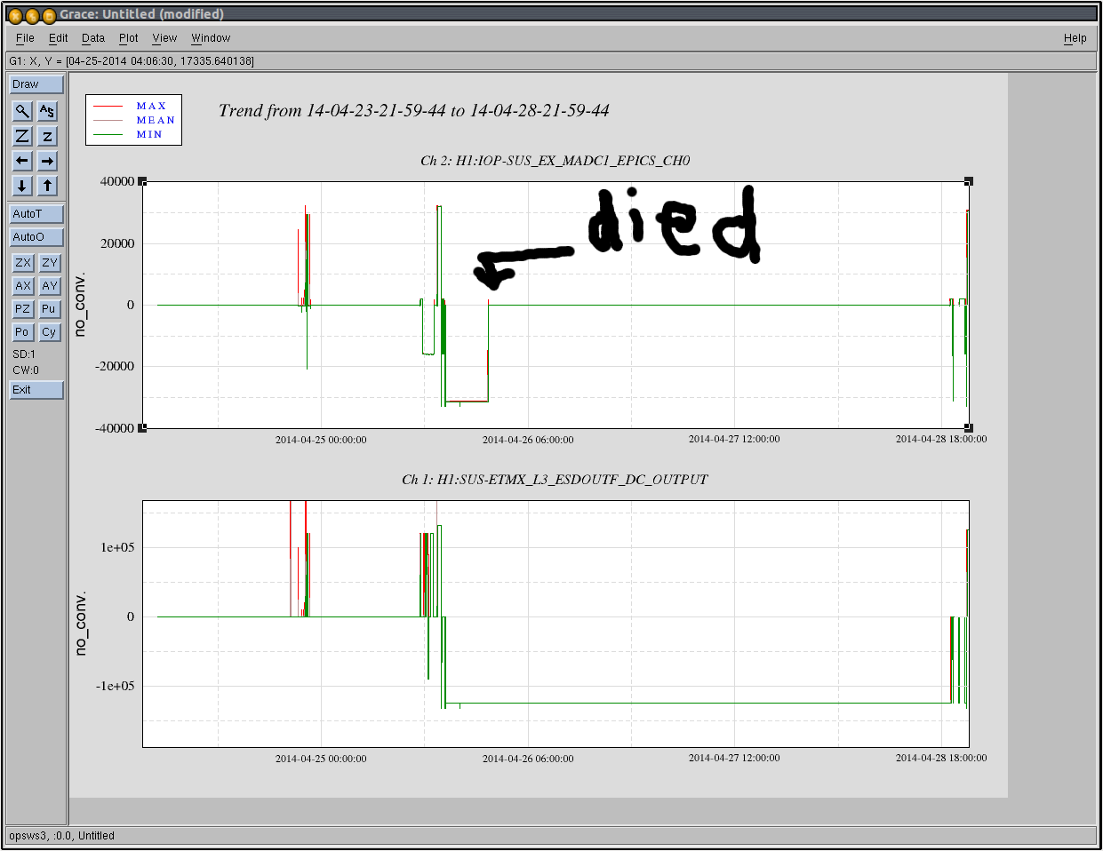
2014_04_29 11:29 h1susetmx
2014_04_29 11:44 h1susetmy
2014_04_29 11:57 h1susetmx
2014_04_29 11:58 h1asc
2014_04_29 12:00 h1isiitmx
2014_04_29 12:10 h1susetmx
2014_04_29 12:12 h1asc
2014_04_29 12:12 h1susetmy
2014_04_29 12:22 h1isiitmx
2014_04_29 12:26 h1isiitmx
2014_04_29 12:29 h1sustmsx
2014_04_29 12:33 h1isiitmx
2014_04_29 12:34 h1sustmsy
2014_04_29 12:35 h1isiitmx
2014_04_29 12:49 h1isiitmx
2014_04_29 12:57 h1broadcast0
2014_04_29 12:57 h1dc0
2014_04_29 12:57 h1fw0
2014_04_29 12:57 h1fw1
2014_04_29 12:57 h1nds0
2014_04_29 12:57 h1nds1
2014_04_29 13:10 h1isiitmx
2014_04_29 13:25 h1isiitmy
2014_04_29 13:34 h1iscex
2014_04_29 13:36 h1iscey
2014_04_29 13:41 h1iscey
2014_04_29 13:41 h1isietmx
2014_04_29 13:47 h1isietmy
2014_04_29 13:55 h1isibs
2014_04_29 14:44 h1iscex
2014_04_29 14:45 h1iscey
2014_04_29 15:19 h1susomc
2014_04_29 16:03 h1susitmx
2014_04_29 16:07 h1susitmy
2014_04_29 16:11 h1iscex
2014_04_29 16:12 h1susetmx
2014_04_29 16:19 h1susetmy
2014_04_29 16:25 h1susbs
2014_04_29 16:32 h1suspr3
2014_04_29 16:42 h1susmc1
2014_04_29 16:43 h1susmc3
2014_04_29 16:45 h1susprm
2014_04_29 16:51 h1susmc2
2014_04_29 16:53 h1suspr2
2014_04_29 16:57 h1sussr2
2014_04_29 16:59 h1sussr3
2014_04_29 17:01 h1sussrm
2014_04_29 17:02 h1sussrm
2014_04_29 17:04 h1broadcast0
2014_04_29 17:04 h1dc0
2014_04_29 17:04 h1fw0
2014_04_29 17:04 h1fw1
2014_04_29 17:04 h1nds0
2014_04_29 17:04 h1nds1
2014_04_29 17:10 h1sussr2
2014_04_29 17:53 h1susetmy
No unexpected restarts. A very busy maintenance day.