WP#4569 Change name of h1peml0 model (Dave)
The name of the model h1peml0 was changed to h1pemcs to be consistent with the naming scheme and the internal channel names. The required changes to rtsystab, testpoint.par, master (daq), overview MEDM screens, H1EDCU_DAQ.ini
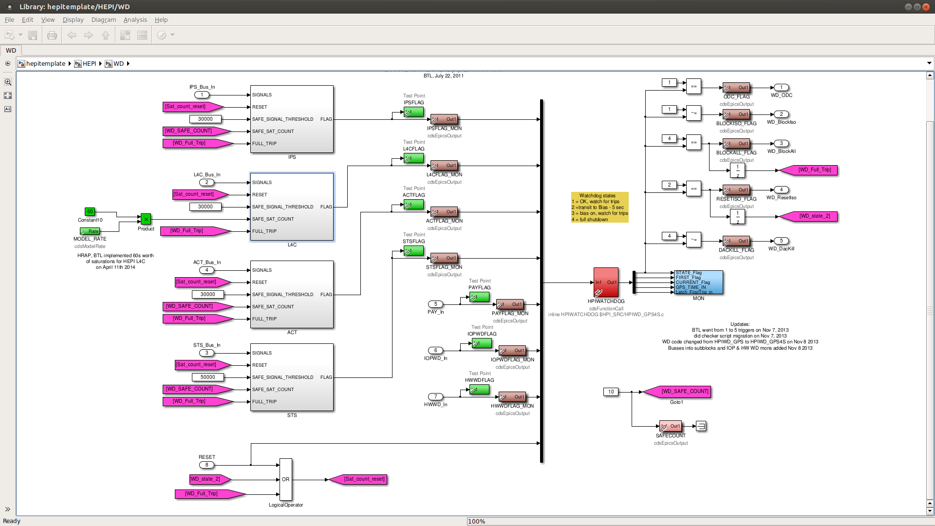
WP#4567 New HEPI models (Brian, Hugo, Hugh and Dave)
The new hepitemplate.mdl file was updated, and all eleven HEPI models were compiled and installed. At that point Hugo restarted the models and performed testing with Hugh. Please see Hugo's alog for details.
Weather Stations Added to DAQ
H0EDCU_WEATHER.ini was modifed to add back the EY and MY weather stations to the DAQ.
Digital Video EPICS channels added gto DAQ
A new H1EDCU_DIGVIDEO.ini file was created with all the EPICS channels for cameras 1 through 20. This was added to the DAQ master.
Beckhoff INI and REQ updates
The latest Beckhoff INI and REQ files were generated. No change to the INIs. One REQ channel was removed from ECATY1_PLC2. This required a reconfiguration of conlog, whose channel count decremented from 122,675 to 122,674.
DAQ Restart
To apply the pemcs and weather changes, the DAQ was restarted at 12:15PDT.
restart logs:
2014_04_15 11:35 h1hpiham4
2014_04_15 11:38 h1pemcs
2014_04_15 12:15 h1broadcast0
2014_04_15 12:15 h1dc0
2014_04_15 12:15 h1fw1
2014_04_15 12:15 h1nds0
2014_04_15 12:15 h1nds1
2014_04_15 12:16 h1broadcast0
2014_04_15 12:16 h1fw0
2014_04_15 12:20 h1hpiham5
2014_04_15 12:23 h1hpiham2
2014_04_15 12:23 h1hpiham3
2014_04_15 12:26 h1hpibs
2014_04_15 12:26 h1hpiitmx
2014_04_15 12:26 h1hpiitmy
2014_04_15 12:28 h1hpietmx
2014_04_15 12:28 h1hpietmy
2014_04_15 12:29 h1hpiham6
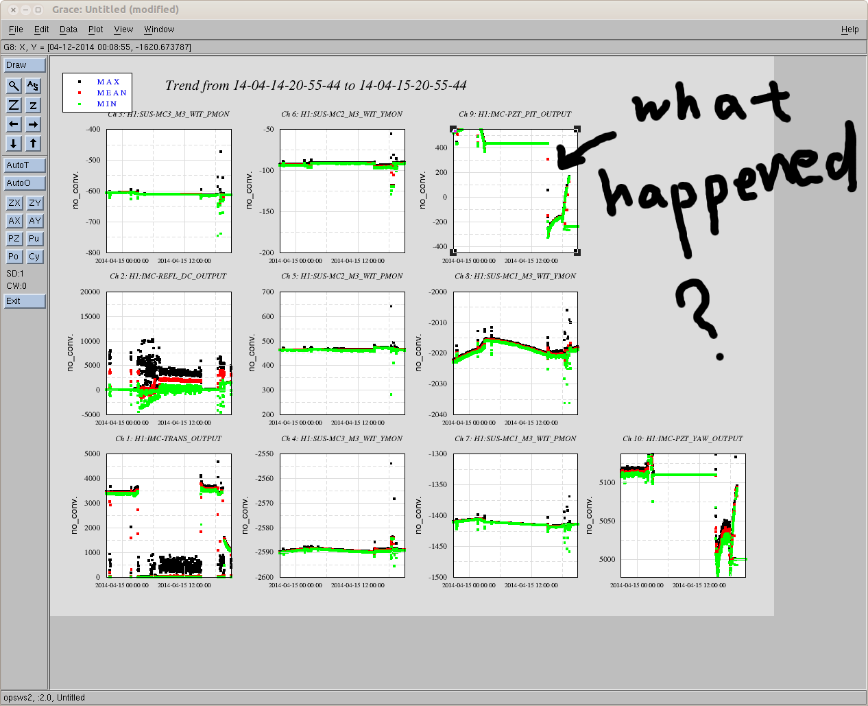


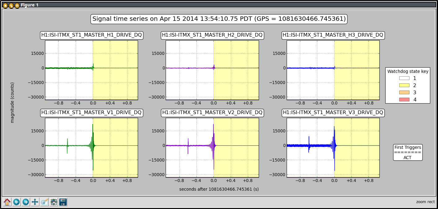
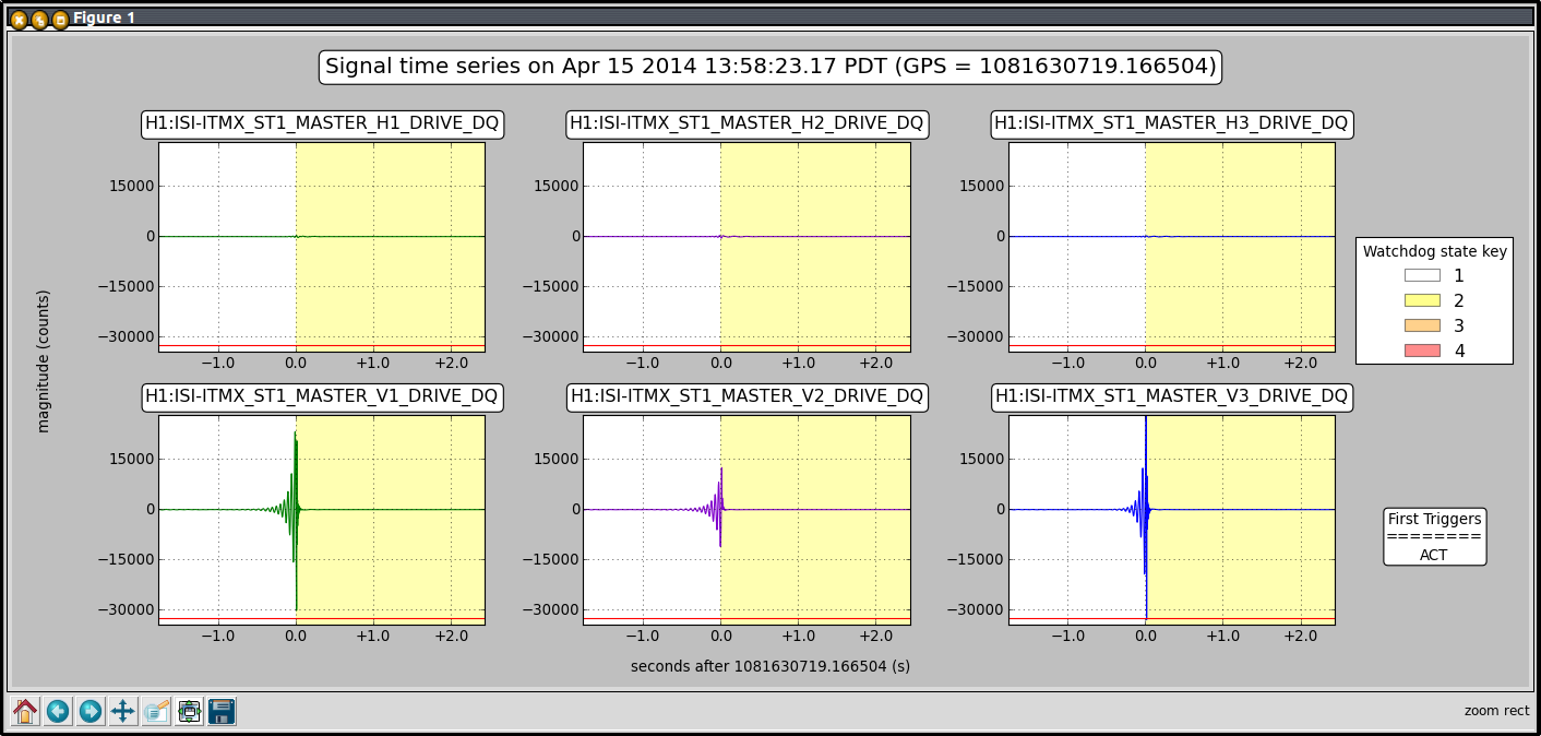
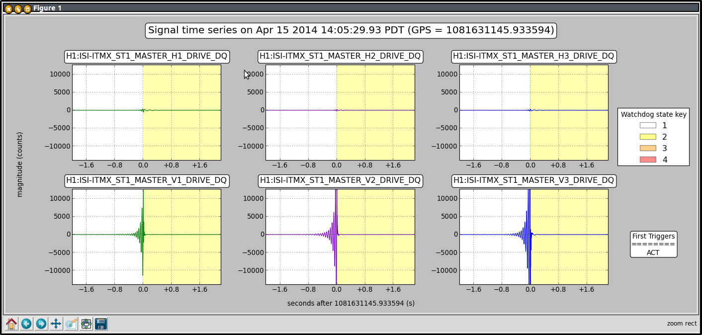
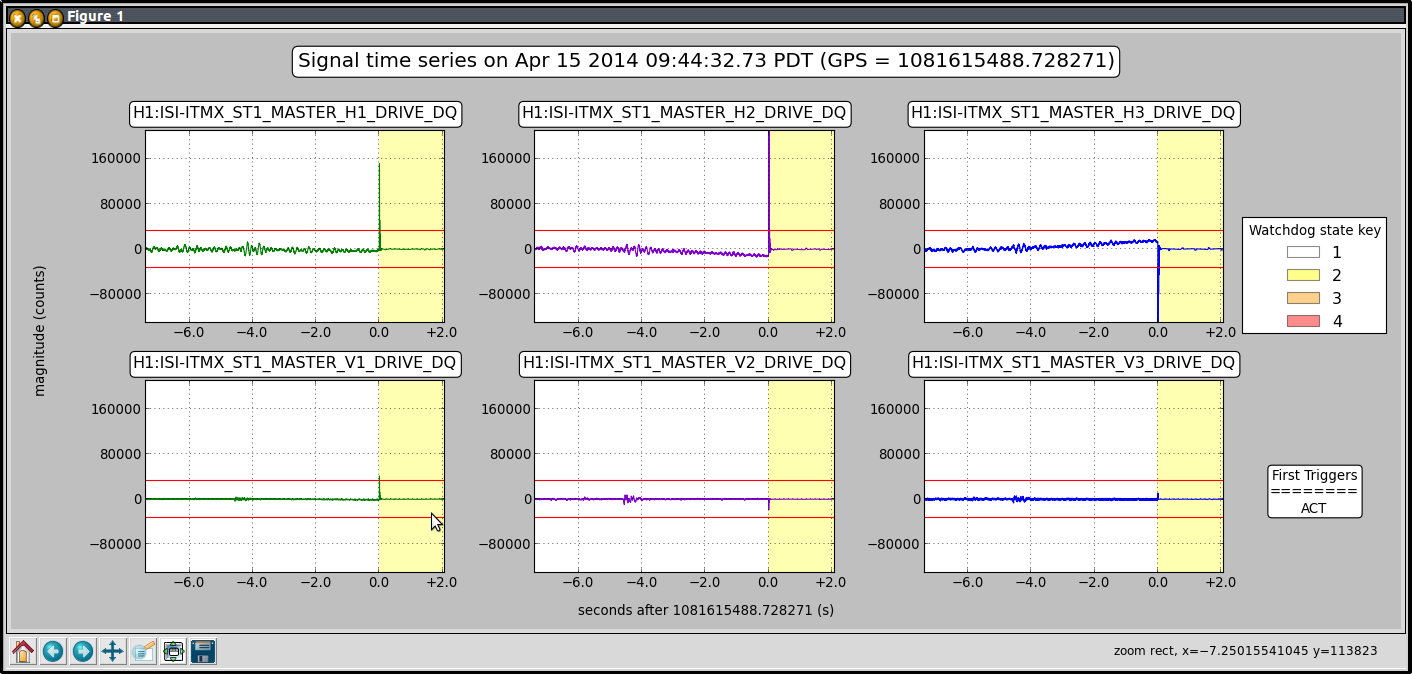

Don't know why it tripped