Jim B, Filiburto, Jim W, Dave
we powered down h1seih45 computer and its IO Chassis. Filiburto installed a fourth binary cable to the output port of the second Contec card (HAM5's card). He disconnected HAM4's CN-B from the upper 32 channel input of the binary-output chassis and connected HAM5's CN-A to this port.
We powered up the system, verified that the new logging script worked.
Jim W verified binary output switching for both HAM5 and HAM4 is working correctly.
reboot log shows the startup as:
2014_04_09 12:17 h1hpiham4
2014_04_09 12:17 h1hpiham5
2014_04_09 12:17 h1iopseih45
2014_04_09 12:17 h1isiham4
2014_04_09 12:17 h1isiham5
2014_04_09 12:17 h1iopseih45
2014_04_09 12:17 h1isiham4
2014_04_09 12:17 h1isiham5


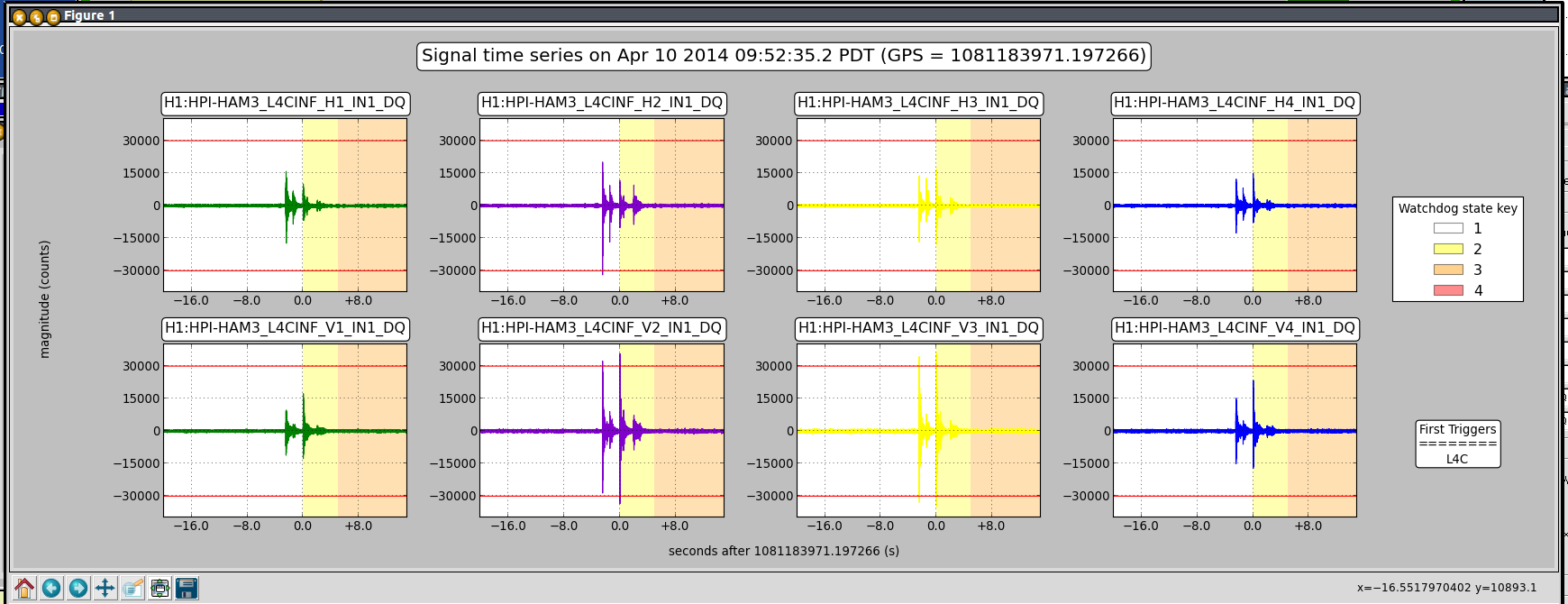
ITMX and ITMY both tripped in the last few minutes. Jim is recovereing. Phil and Aaron are pulling cables, these might be a good example of times when overly sensitive watchdogs make it difficult to commision while there is normal install activity in the LVEA.
Jim, Rich, Sheila,
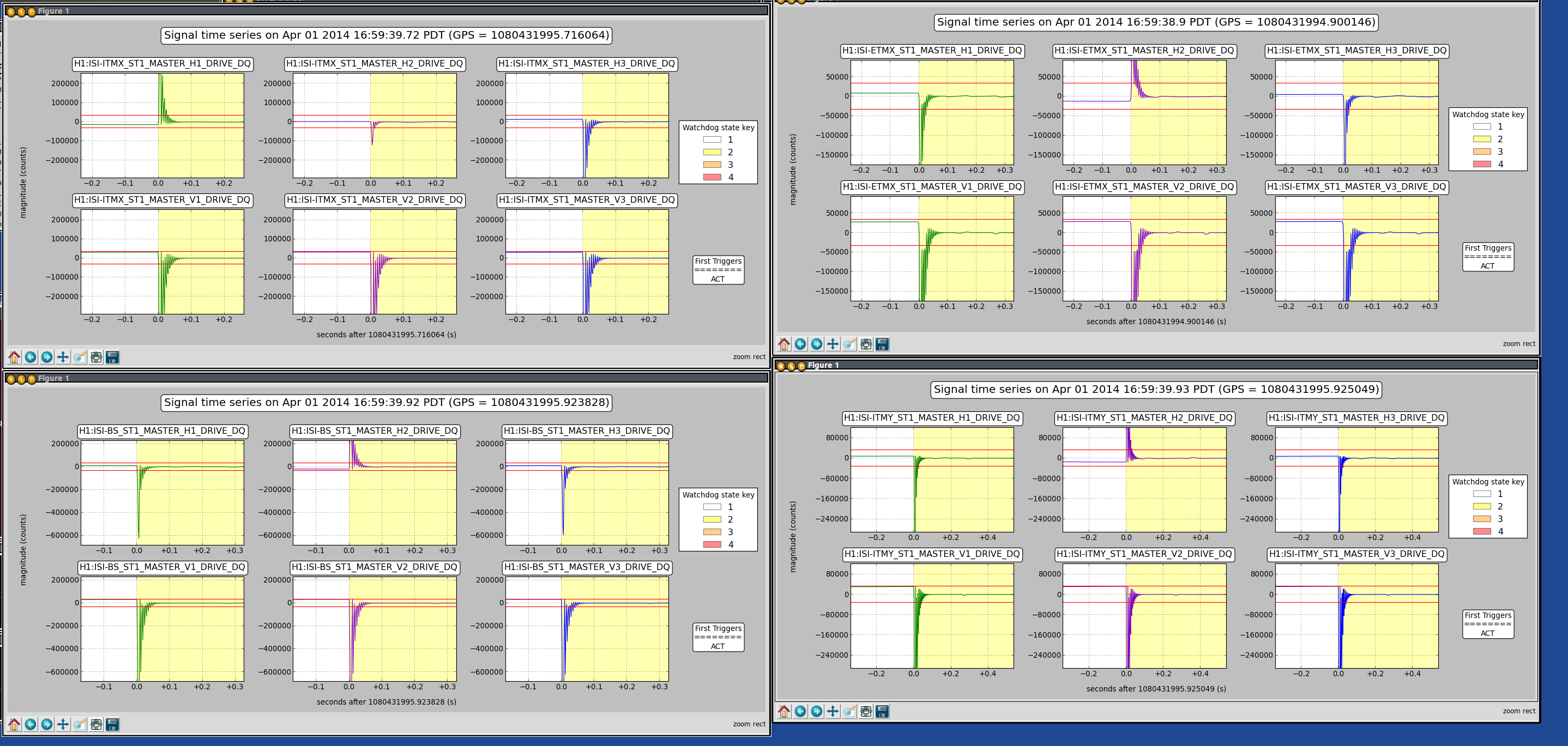
several more trips, BS, both ITMs.
Rich and I tried to put ITMX into a safe state:
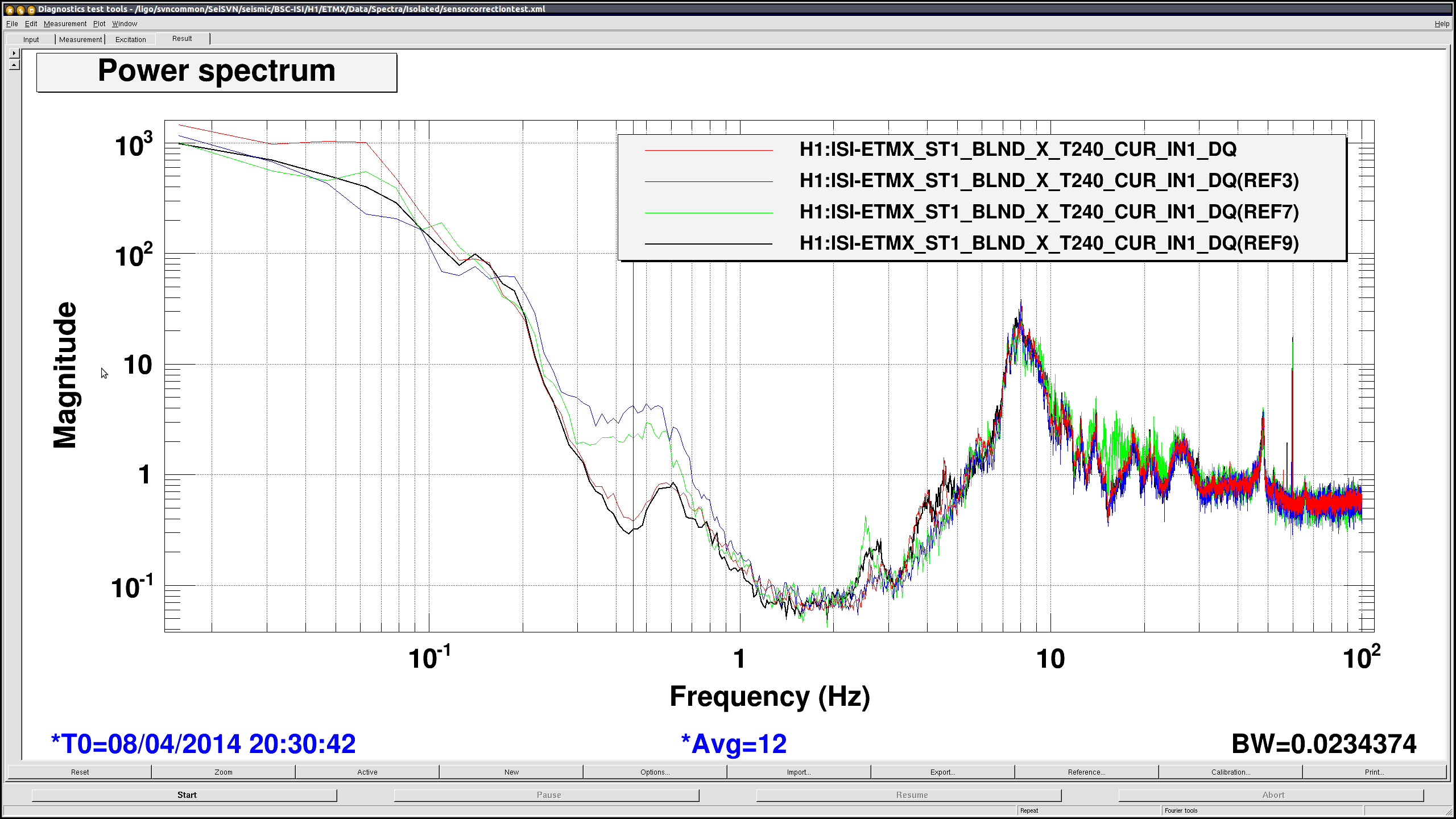
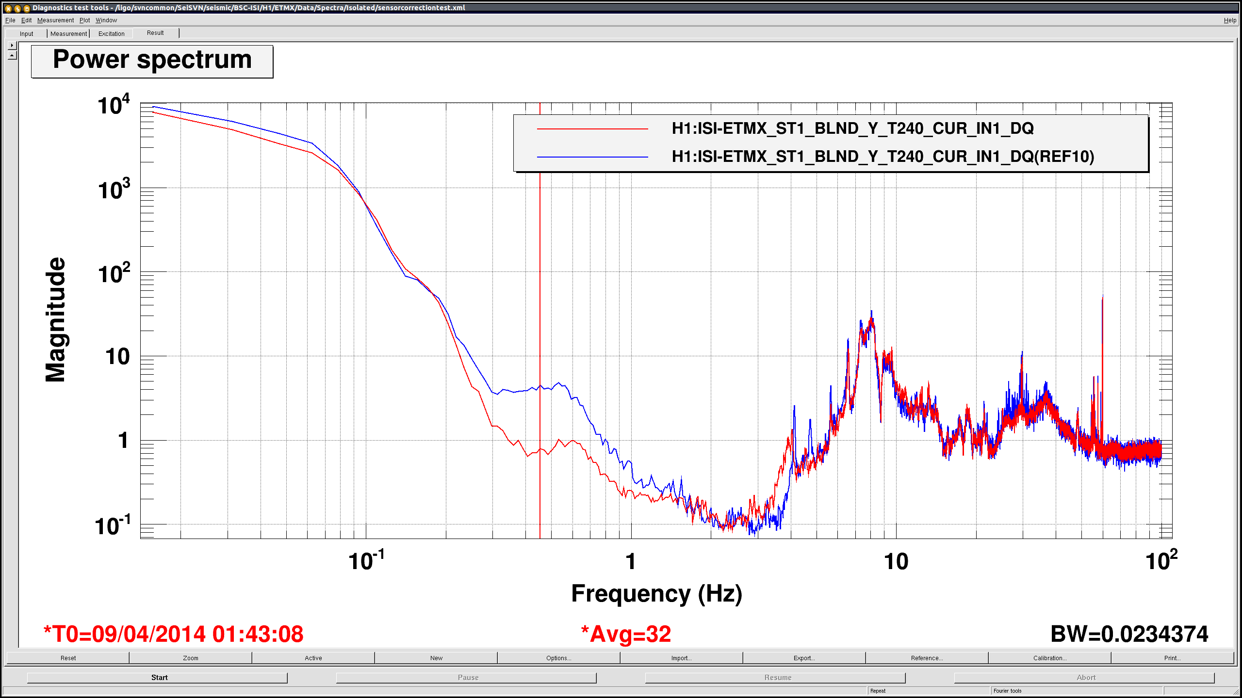
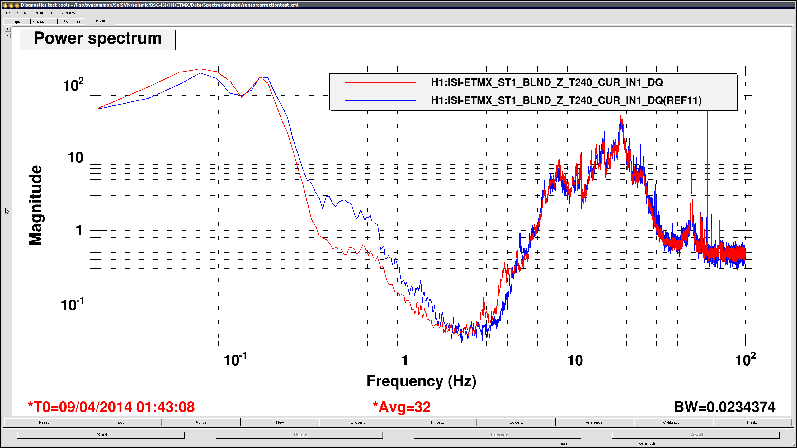
GS13 and L4Cs in low gain mode, all blends on Start, raise T240 watchdog threshold, Sensor correction off.
After we heard that Fil and Aaron are out of the LVEA I tried switching back to the good performance state, it trippped again while I was switching blends.
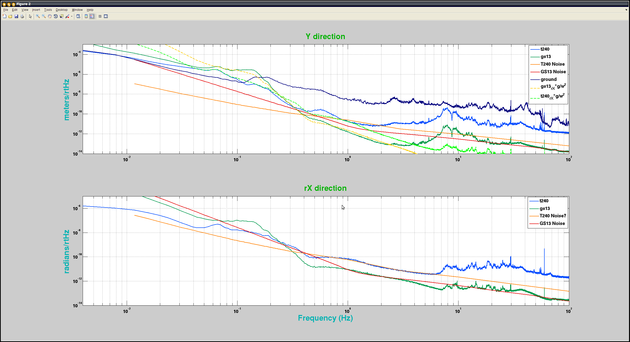
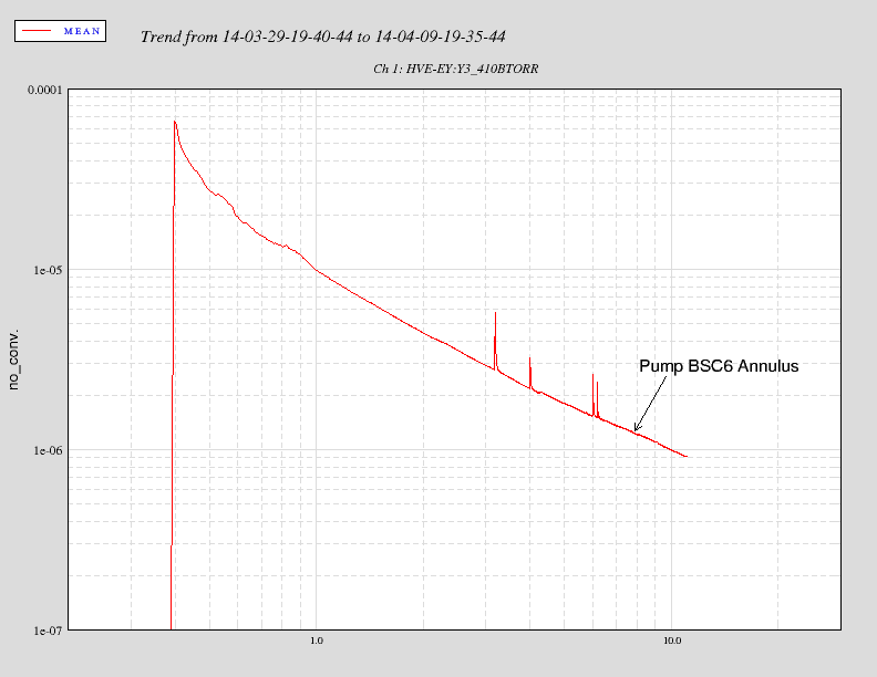
Why do these trip while switching blends? According to Rich that shouldn't happen, but it does. The second attached plot below is the actuator trip that happened while I was switching blends.