Summary: moving both red and green beams to a single periscope seems to have greatly reduced the periscope contribution to the RMS. In HIFO-Y the contribution was about 7 Hz while in HIFO-X, after the move, it is roughly 0.5 Hz. About half of the current HIFO-X periscope peak contribution comes from the periscope on ISCT1 (65-75, 95-105 Hz in the spectrum) with the rest coming from the periscope inside HAM1 (the 68 Hz sharp peak). The forest of peaks between 250 and 700 Hz come from optic supports along the beam paths on ISCT1.
I investigated vibrational noise in the current HIFO-X spectrum. Figure 1 shows coherence between H1:LSC-REFL_SERVO_SLOW_OUT_DQ and the environmental sensors with the most coherence, accelerometers on the ISCTEX table at EX, and the PSL and ISCT1 periscopes at the corner station. Vibration is the source of most of the signal 60 - 900 Hz, and may also become dominant at lower frequencies as other noise sources are reduced. Of course vibrational levels in the region around 100 Hz are now roughly a factor of two or three above what we hope they will be in science mode.
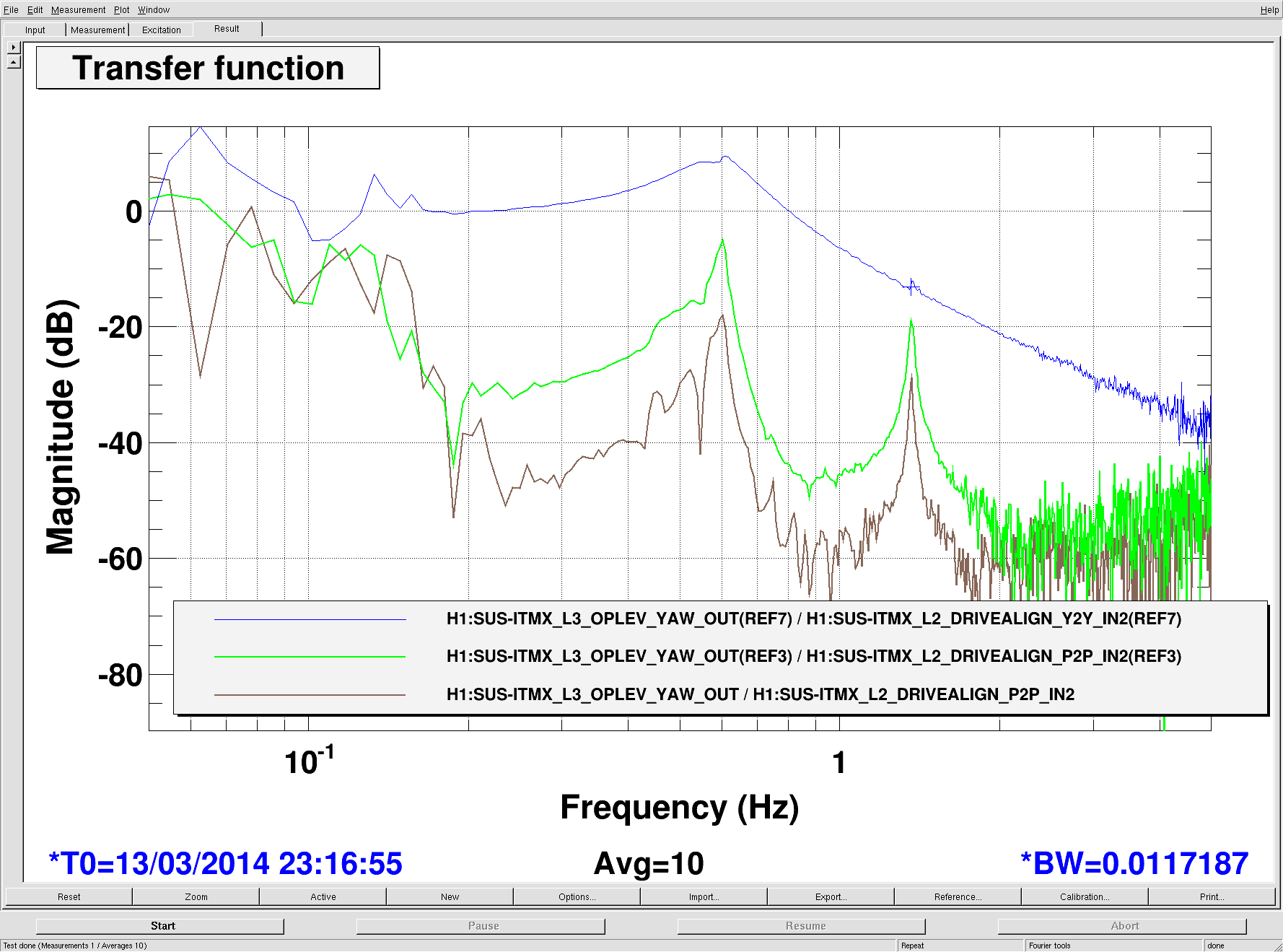
I tap tested ISCT1 while the arm was locked to confirm that the broad peaks in the HIFO-X spectrum at 65-75 Hz and 95-105 Hz were due to the ISCT1 red/green periscope. They do not closely follow the shape of the periscope peak in the accelerometer on the periscope (Figure 1), probably because the features in the HIFO-X spectrum are produced by differences in periscope motion along the red and green path, not total motion. Tap testing also showed that the forest of peaks between 250 and 700 Hz is mainly due to individual optic supports along the red and green paths on ISCT1.
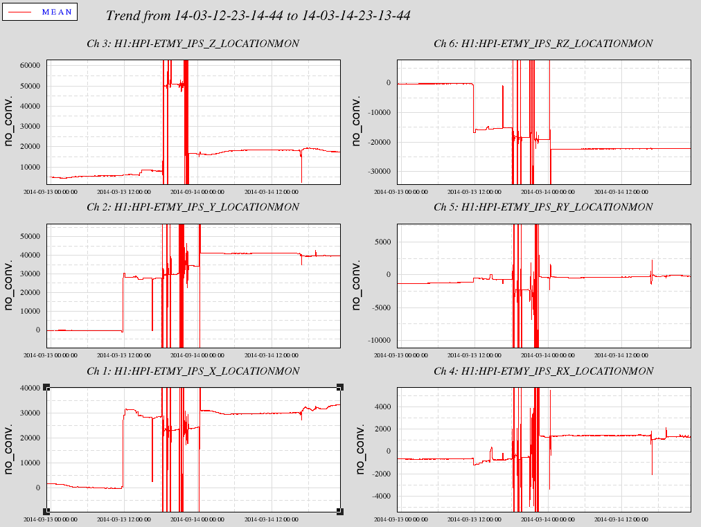
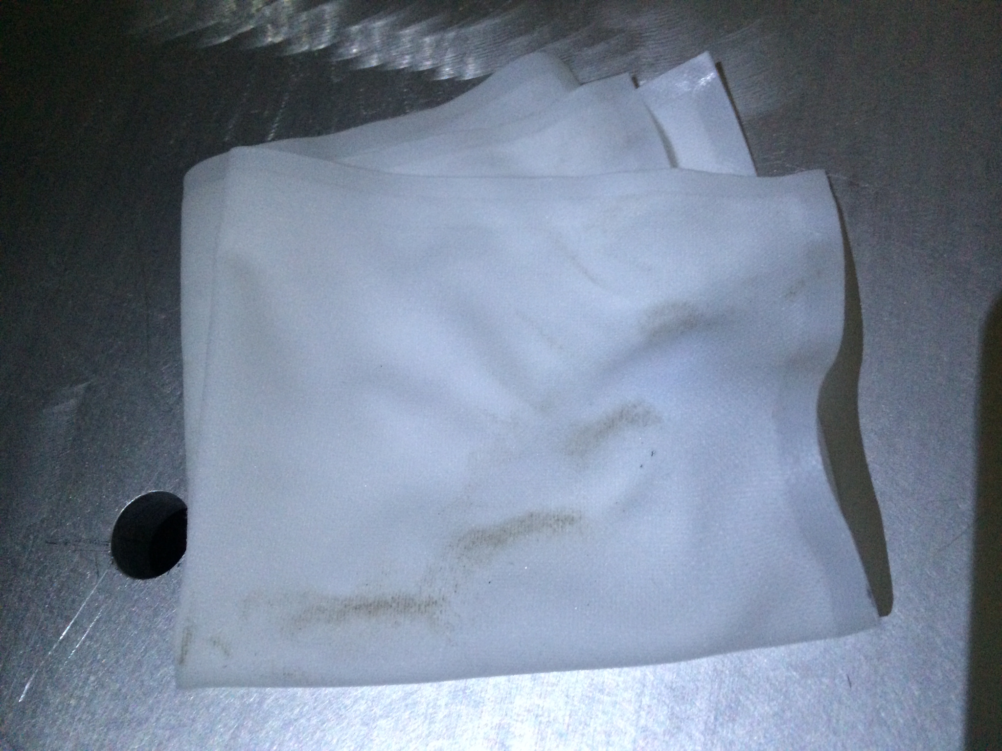
Tap testing did not excite the sharp 68 Hz peak that sits on top of the ISCT1 periscope peaks. Figure 2 shows that I was instead able to excite it with a frequency-sweeping shaker on a blue cross beam of HAM1. The lower plot in Figure 2 shows that the shaker could not have been exciting HAM2 or ISCT1 enough to produce the peak, supporting the conclusion that the peak is due to motion inside HAM1. A very likely source of the 68 Hz peak is the tall periscope inside HAM1 (shown in Figure 3) used to direct the beams to the red/green periscope on ISCT1. Other optic supports in HAM1 should have much higher frequencies.
Moving the two beams onto a single periscope, suggested by Stefan, seems to have worked very well. In HIFO-Y the red and the green ISCT1 periscopes added about 7 Hz to the HIFO-Y RMS (here). In Shiela’s calibrated H1:LSC-REFLBIAS_OUT spectrum, with the calibration thought to be good to a factor of a couple at this frequency, the 65-75, 95-105 Hz portion of the ISCT1 periscope peak adds about 0.20 Hz to the RMS. The 68 Hz HAM1 periscope peak adds about 0.17 Hz (it added a lot more before the clean room was turned off).