keita.kawabe@LIGO.ORG - posted 17:48, Thursday 13 March 2014 - last comment - 10:21, Friday 14 March 2014(10747)
ETMX PUM Y2P decoupling done
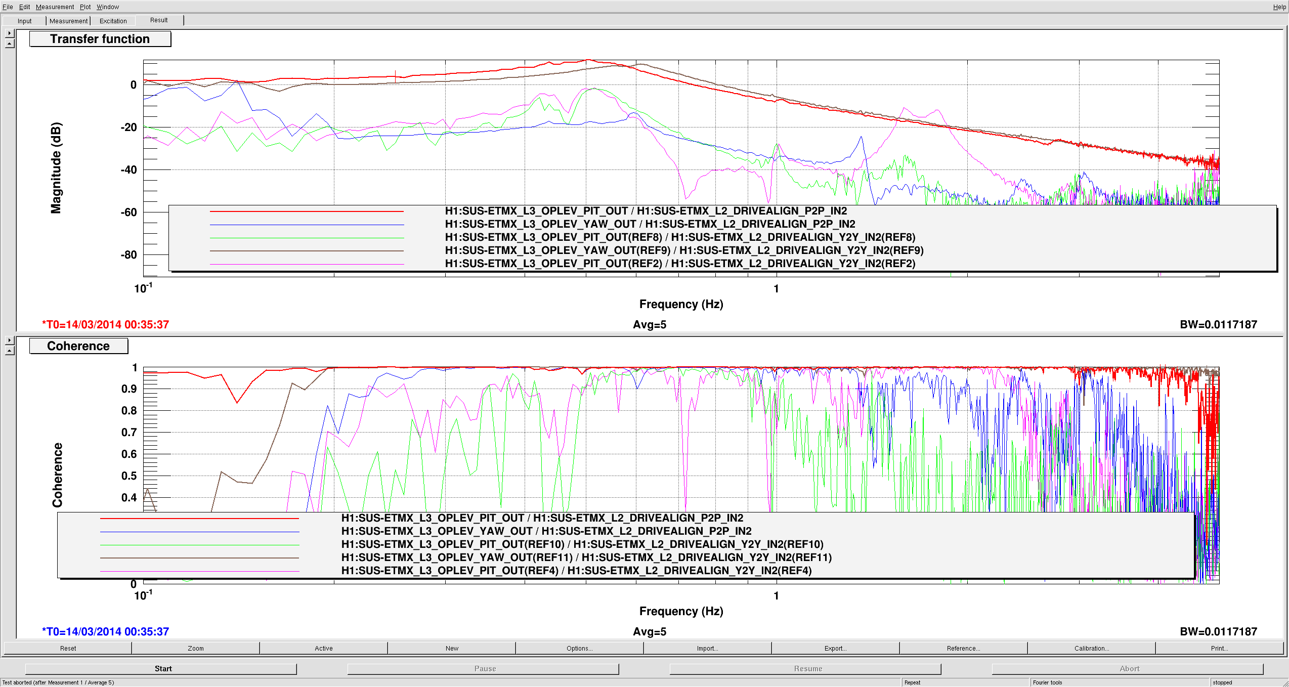
Offending Y2P peak between 1 and 2Hz (pink) was removed after a new decoupling filter was put in place (green).
In the H1:SUS-ETMX_L2_DRIVEALIGN_Y2P filter, I put the same invP2P filter in FM1 as in the P2P path, then added a diagonalization filter ("Y2Pdiag") in FM2, and another filter that is a 3rd order elliptic BP in FM3. I didn't try to remove 0.4-0.5Hz Y2P peak, it's not great but probably good enough.
Images attached to this report
Comments related to this report
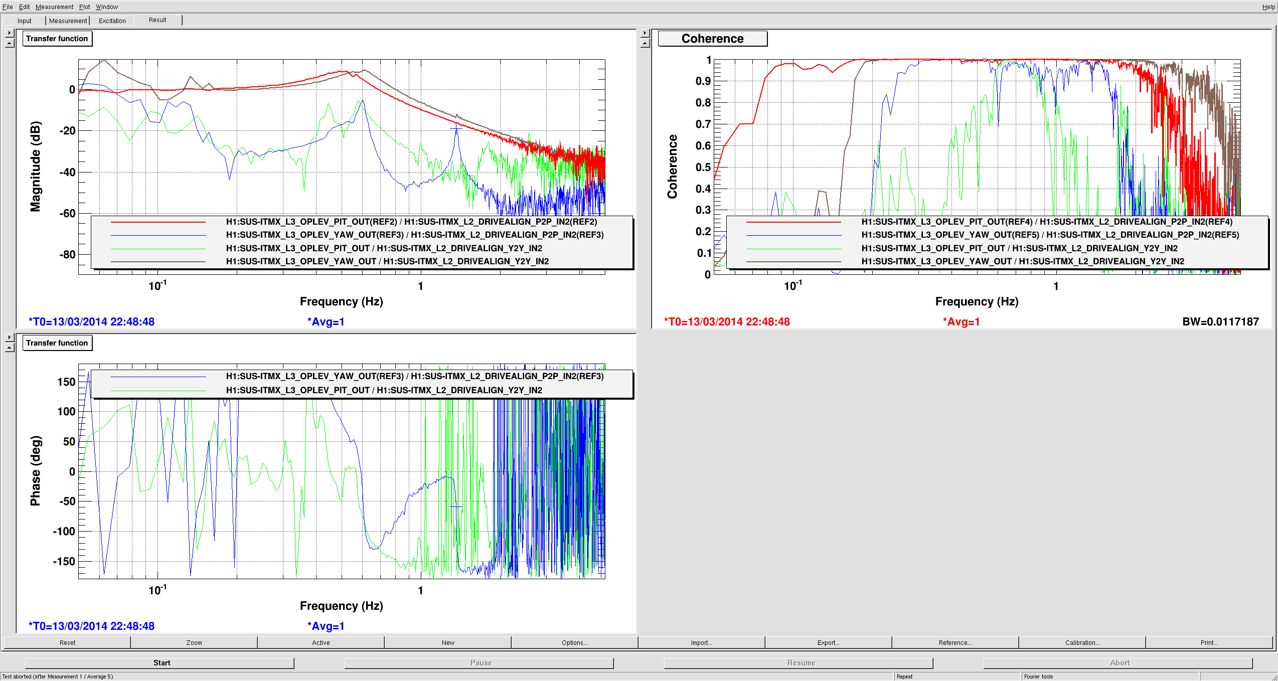
ITMX PUM P2Y and Y2P measurement was done, but I need to leave before generating decoupling filter.
Seems like ITMX PUM is somewhat better diagonalized than ETMX PUM, but I'll remove 1.4Hz P2Y peak anyway.
Images attached to this comment
Remember, the ITM is a wire hang QUAD (the test mass is suspended from the PUM via a wire loop and prisms), and has significantly different dynamics than the ETM fiber welded QUAD. This may be an explanation for the different dynamics.

I also imagine you'll have to do this process all over again with the ITM once it becomes monolithic like the ETM.
We probably need to re-do everything once it's re-hang.